
Rotary Airlock Valves
How Does a Rotary Airlock Valve Work? A Practical Guide for Plant Engineers

Vijay Baid
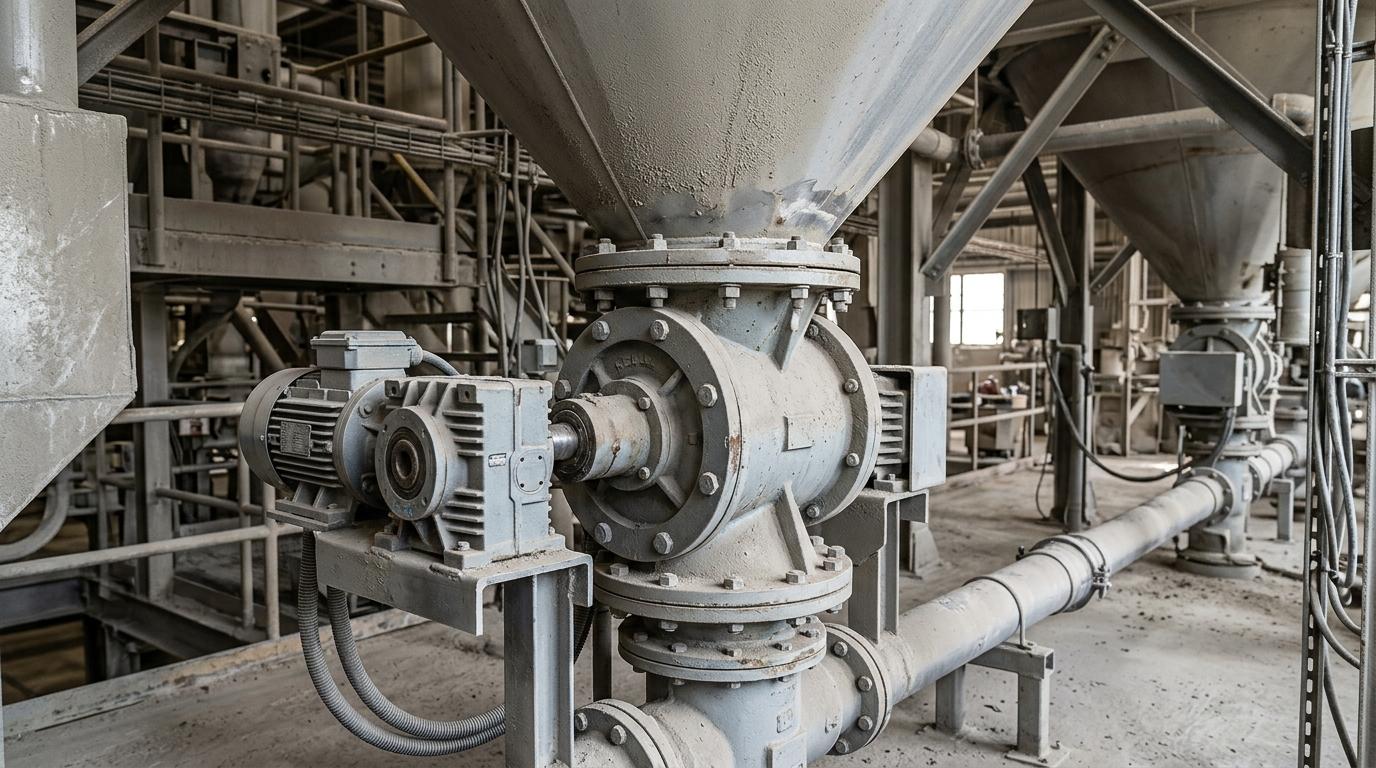
TL;DR: A rotary airlock valve moves bulk solids by filling rotor pockets at the inlet, carrying them through the housing, and releasing them at the outlet while limiting air leakage between pressure zones. Its performance depends on pocket fill, rotor speed, vane and rotor design, venting, and tight internal clearances.
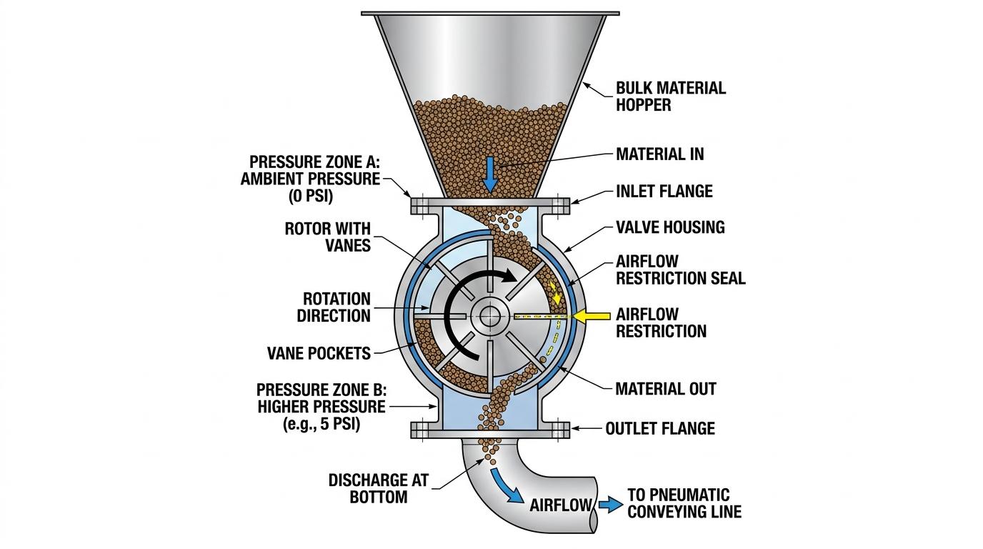
A rotary airlock valve moves bulk solids from one pressure zone to another while the rotor turns inside a precisely machined housing. Material enters the pockets at the top, travels around with the rotor, and drops out at the bottom. At the same time the vane tips and housing walls limit air movement across the valve.
This guide walks through the mechanical sequence, the main components, the different rotor and body styles, and the factors that control pocket fill and seal performance.
Core components and their roles
A standard rotary airlock consists of five main elements:
Housing (body and end covers) :heavy-duty cast or fabricated cylinder with inlet and outlet flanges. The bore is machined to tight tolerance.
Rotor :multi-vane assembly (usually 6, 8, or 10 vanes) fixed to a central shaft. The spaces between vanes form the pockets that carry material.
Shaft, bearings, and seals :support the rotor and keep material and air from escaping at the ends. Outboard bearings are common on higher-pressure designs.
Drive package :electric motor and gearbox, usually chain- or direct-coupled. Typical speeds are 10–25 rpm.
Optional features :adjustable tips, vent ports, purge connections, and wear liners.
The housing and rotor must be machined so that the clearance between vane tips and bore stays in the 0.004–0.006 in range under operating temperature. That gap is what allows rotation while restricting air flow.
Step-by-step operating sequence
1. Empty pockets arrive at the inlet throat under the feed hopper or collector.
2. Material falls by gravity into the open pockets. Fill percentage depends on material flow properties, throat geometry, rotor speed, and the way upstream screw conveyors deliver material into the inlet.
3. The rotor turns and carries the loaded pockets past the housing wall. At least two vanes remain in contact with the bore on each side of the valve, creating a multi-stage barrier.
4. At the bottom outlet the pockets empty. In a drop-through design the material simply falls out into a hopper, chute, or downstream belt conveyor system; in a blow-through design conveying air sweeps the pockets clean.
5. Empty pockets continue upward. Any trapped air or residual material is managed by the vent port (if fitted) before the pocket returns to the inlet.
The cycle repeats continuously. Throughput equals pocket volume × number of pockets × rotor speed × fill efficiency.
Rotor styles and what they change
The two main rotor constructions used in plant service are compared below.
Rotor type | Description | Best fit | Sealing performance | Key trade-off |
|---|---|---|---|---|
Open-end | Vanes extend the full width to the end covers. | Higher pressure differential applications where tighter air control matters. | Higher, because more sealing surface stays close to the housing. | Fines can migrate toward the shaft seals and surface contact is higher. |
Closed-end (shrouded) | Side discs close off the vane ends. | Abrasive or high-temperature service where wear and thermal growth are bigger concerns. | Lower than open-end designs, but often more practical in harsh service. | Protects end covers from wear and makes thermal-expansion clearance easier to manage. |
Open rotors generally give a tighter air barrier because more metal surface is in close proximity to the housing. Closed rotors keep abrasive particles away from the end covers and are often preferred in tougher industry applications.
Vane count also matters. More vanes increase the number of sealing points in contact at any moment and reduce the volume of each individual pocket. Eight or ten vanes are common when differential pressure is significant.
trusttedIf you need a faster technical reference, download the spec sheet to review key design details, operating considerations, and solution fit before your next discussion or plant review.
Drop-through versus blow-through body styles
- Drop-through: material exits the bottom flange by gravity into a transition piece or conveying line adapter. Most common general-purpose arrangement.
- Blow-through: the conveying pipeline connects directly to the end covers so that air flows through the rotor pockets themselves. Useful for cohesive materials that tend to stick and for installations with limited headroom.
Side-entry designs shift the inlet to the side of the housing. They reduce the risk of material flooding the rotor and are sometimes preferred where upstream slide gates are used for isolation or controlled discharge.
What controls pocket fill efficiency
Theoretical capacity assumes 100 % fill. Real fill rates are lower:
- Free-flowing granular materials often reach 70–85 %.
- Fine powders and cohesive materials may drop to 40–60 % without proper venting or inlet geometry.
- Rotor speed above roughly 25–30 rpm usually reduces fill because the pockets spend less time under the inlet.
- Air leakage rising through the empty returning pockets can fluidize light powders and further cut fill. Where dust generation is a plant concern, NIOSH dust-control guidance for conveying operations is a useful reference point.
A body vent or vented transition above the valve lets leakage air escape before it reaches the feed material. In broader dust-control layouts, dampers can also help balance airflow while the valve handles solids transfer. For dust-explosion prevention context in powder-handling systems, see this HSE guidance on combustible dust precautions.
Sealing geometry in practice
The valve never creates a perfect seal. Air moves through the tip-to-housing clearance and is also carried in the empty pockets (dynamic leakage). The design keeps both paths small enough that system pressure stays within acceptable limits. For safety context where dry particulate hazards are present, OSHA’s combustible dust directive specifically discusses rotary valves within bulk solids handling systems.
Key geometric factors:
Tip clearance and length of the sealing arc between vanes and bore.
Number of vanes in continuous contact.
Shaft-seal arrangement (packing, lip seals, or purge air).
Housing stiffness so that pressure differential does not open the bore.
Thermal expansion must be accounted for in the clearance specification. Hot materials require additional diametral clearance so the rotor does not seize when it reaches operating temperature.
Drive and speed considerations
Most valves run well below the speed that would produce high tip velocity. Tip speeds above about 40 m/min begin to reduce fill and increase wear. Gearbox ratio and motor size are selected so that the rotor turns at the speed required for the desired volumetric rate while staying in the efficient range.
Variable-frequency drives are common when the feed rate must change with process demand. Because the valve is volumetric, speed changes give a reasonably linear change in throughput for free-flowing materials. In larger bulk-handling layouts, the valve often works alongside conveyors whose conveyor pulleys and drive settings also affect overall line reliability. Where sizing or control is still uncertain, a product consultation can help match the valve, drive, and operating window to the application.
Need help selecting the right rotary airlock valve for your material, pressure conditions, or operating temperature? Talk through your application with an engineer to get practical guidance on sizing, rotor style, sealing, and installation fit.
Summary of the working principle
Material fills rotor pockets at the inlet, is carried around the housing by slow rotation, and discharges at the outlet. Simultaneously the tight tip clearances and multiple vane contacts restrict air movement between the two pressure zones. Pocket volume, rotor speed, fill efficiency, and clearance geometry together determine both the material rate and the quality of the air barrier.
Key takeaways
The valve is a rotating pocket conveyor with a precision air barrier built into the same geometry.
Open-end rotors favor sealing surface area; closed-end rotors favor abrasion and temperature resistance.
Drop-through and blow-through bodies suit different headroom and material-flow conditions.
Real capacity is pocket volume × speed × fill efficiency; fill is rarely 100 %.
Clearance, vane count, and venting control how much air crosses the valve during rotation.
Frequently asked questions
Empty pockets fill under the inlet, the rotor carries the loaded pockets past the sealing surfaces, material discharges at the bottom, and empty pockets return to the inlet. Throughout the cycle multiple vanes stay in contact with the housing bore to limit air transfer.
Open-end vanes reach the end covers and provide more sealing surface. Closed-end rotors have side discs that protect the end covers from abrasive particles and simplify thermal-expansion clearances.
Material flow properties, inlet geometry, rotor speed, and air rising through returning pockets all reduce the volume that actually enters each pocket. Free-flowing granules fill better than fine or cohesive powders.
Most industrial valves operate between 10 and 25 rpm. Higher speeds reduce fill efficiency and increase wear; tip speed is usually kept well below 40 m/min.
The small clearance between vane tips and housing bore, combined with the fact that several vanes remain in contact at all times, creates a series of restricted paths. The design minimizes leakage while still allowing the rotor to turn freely.