
Bulk Material Handling
How to Choose a Flow Control Gate for Silo and Hopper Discharge

Vijay Baid
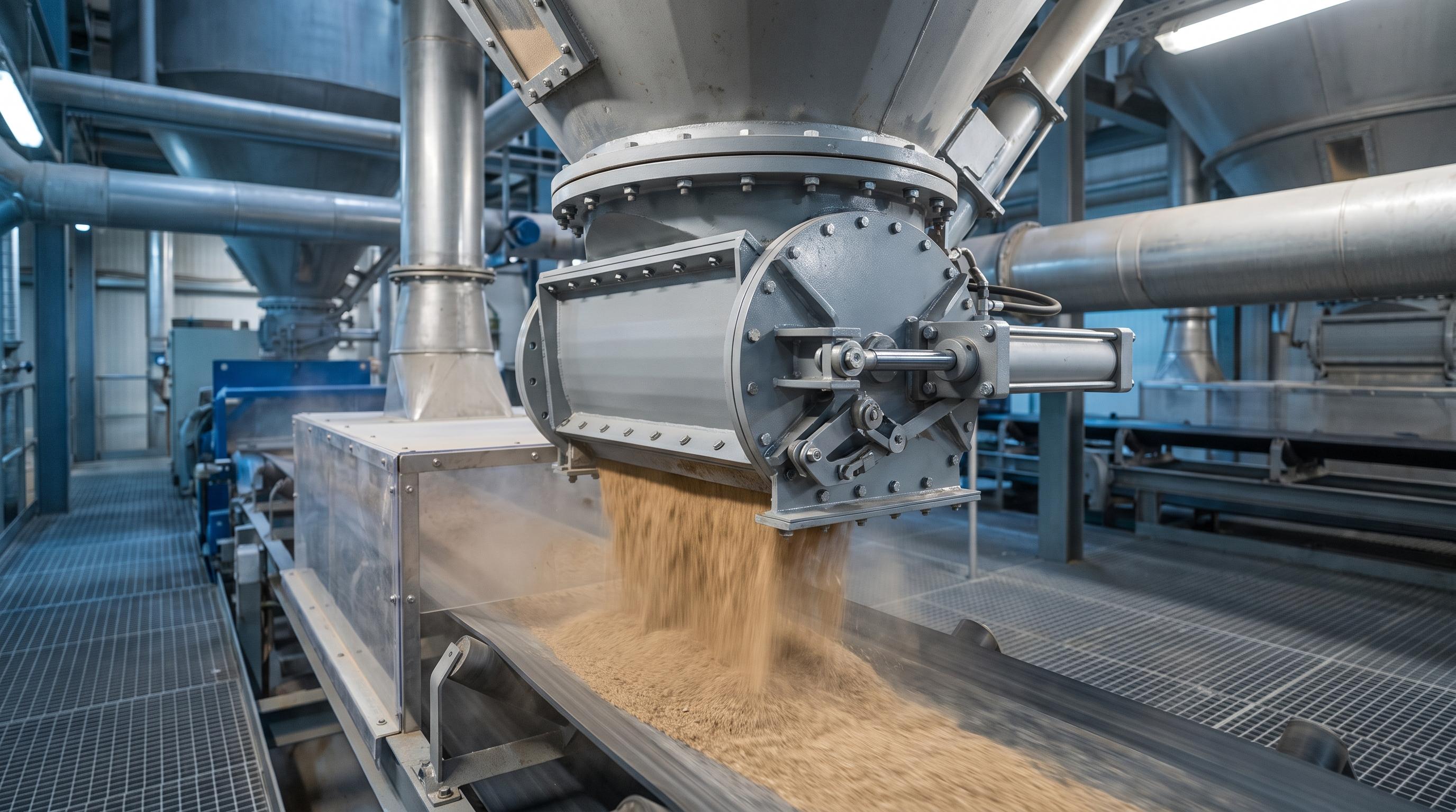
A flow control gate is a modulating gate installed at a silo or hopper outlet to meter dry bulk material through an adjustable opening. It is used when the plant needs a controlled, repeatable discharge rate into a conveyor, feeder, or batch system rather than simple open-or-close isolation. For engineers and buyers evaluating a new installation or a retrofit, that distinction matters because feed stability, dust control, and downstream performance all depend on it.
This guide answers the practical questions that usually decide the purchase: when a flow control gate is the right choice, how it differs from a slide gate, whether the hopper can meter reliably at all, and how to size and actuate the gate for a real operating duty. Get those decisions right on flow pattern, sizing, and actuation, and the gate is far more likely to perform the way the plant expects.
A flow control gate meters the discharge rate through an adjustable opening. A slide gate only isolates. Choose the gate with the hopper, not after it, because a partly open gate under a poorly flowing hopper invites arching and flushing. Size the opening to the throughput you need, and match the actuation to how tightly you control the rate. Add closed-loop feedback when the rate has to stay on target.
When a flow control gate is the right choice
You need a controlled, repeatable discharge rate into a conveyor, feeder, or batch system rather than simple open-or-close isolation.
The hopper or silo can flow cleanly enough to let the gate meter the material without chronic arching, ratholing, or flushing.
The application calls for a held opening, preset positions, or signal-based adjustment instead of a gate that only opens fully or closes fully.
You are evaluating a new installation or a retrofit where feed stability, dust control, and downstream equipment performance all depend on a steady discharge rate.
What a flow control gate does at a silo or hopper outlet
A flow control gate sits at a discharge point: the bottom of a silo, hopper, or bin, or a conveyor feed inlet. In the discharge train, it comes after the outlet and any aeration, and before the feeder and conveyor. Its job is to set and hold the rate at which material leaves.
That adjustable, held rate is what makes it a control device rather than a shut-off. A downstream screw feeder, belt, or weigh batcher needs a predictable feed to run well. The flow control gate is what turns an open silo outlet into a metered feed point.
Flow control gate vs slide gate: modulation vs isolation
A slide gate and a flow control gate are not the same device, even though they look alike and often mount in the same place. A slide gate, sometimes called a knife gate, isolates. It is meant to run fully open or fully closed, and its job is to shut off a silo or line for maintenance. A flow control gate modulates. It holds a partial opening to regulate the rate.
The distinction matters more than it looks. Under a well-designed hopper, a slide or knife gate should run fully open or fully closed, never throttled. A partly open isolation gate chokes the outlet and disturbs the flow the hopper was designed to produce. If you need to hold a rate, you need a gate built to modulate, not an isolation gate held half open.
Device | Primary job | Opening | Metering accuracy | Best use |
|---|---|---|---|---|
Flow control gate | Modulate the discharge rate | Adjustable, proportional | High, with position feedback | Metered feed to a conveyor, feeder, or batcher |
Slide (knife) gate | Isolate, on or off | Fully open or fully closed | None; not for throttling | Shutting off a silo or line for service |
Meter and seal pressure | Fixed pockets, speed-controlled | High, volumetric | Feeding into a pneumatic or pressurized line |
A common arrangement uses more than one. A slide gate sits under the silo for maintenance isolation, a flow control gate meters the rate, and a rotary airlock feeds a pneumatic line. Each does one job well.
Why the hopper's flow pattern decides the gate
The flow pattern of the hopper decides whether a gate can meter at all. Every silo discharges in one of two patterns. In mass flow, all the material moves whenever any moves. In funnel flow, material moves in a central channel while the sides stay dead. The difference between mass flow and funnel flow is set by the hopper angle, the wall friction, and the material, as outlined in the University of Michigan's hopper design reference, and it decides what a gate can and cannot do.
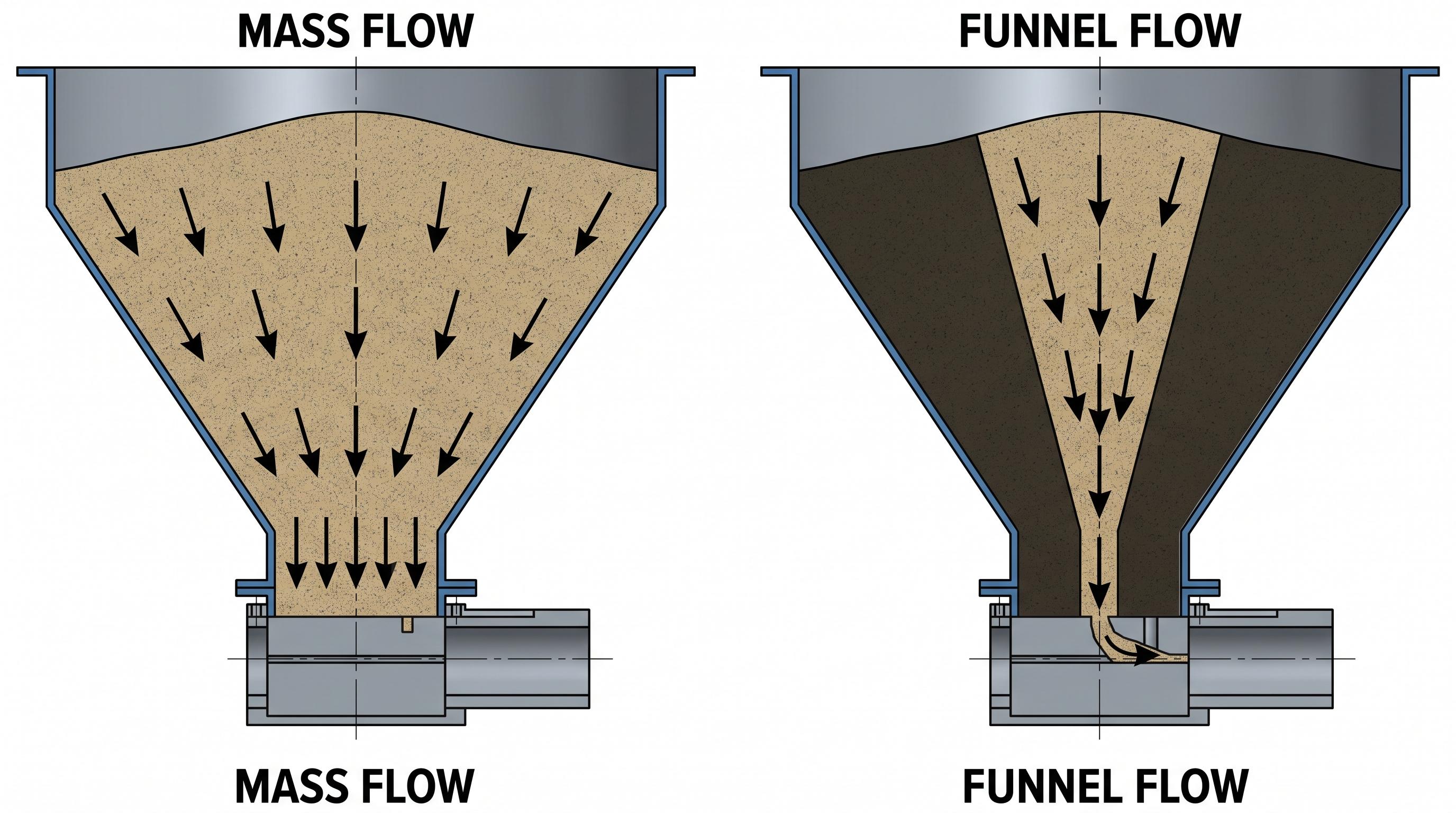
A flow control gate holds a partial opening by design, so over a funnel-flow hopper that partly live outlet can trigger arching, ratholing, flushing, and segregation, and no gate setting fixes any of them. In real retrofit work, that usually shows up as belt-loading swings, skirt leakage, and dust excursions long before anyone blames the hopper. On a duty like clinker reclaim, the fix is usually not a bigger actuator but a proper discharge redesign: check the chute geometry with DEM simulation, build the gate body to the wear duty with abrasion-resistant surfaces in the high-velocity zones, and size the opening range around the live outlet rather than the flange. That is why the gate has to be chosen with the hopper and feeder, not bolted on afterward, especially where dust control and EPA-facing compliance pressure matter.
Field rule: Choose the gate with the hopper, not after it. A partly open gate under a funnel-flow hopper creates a partly live outlet, which invites arching, ratholing, and flushing that no gate setting can correct.
How to size a flow control gate to your discharge rate
Sizing starts from one fact: a gate can only reduce the rate below what the outlet and hopper already allow. It cannot pull material faster than the outlet flows.
For coarse, free-flowing solids, estimate the maximum gravity discharge rate first from the outlet size, bulk density, and hopper geometry. The Beverloo equation is a standard engineering starting point, and more recent discharge-rate work on mass-flow and funnel-flow hoppers provides a stronger technical reference for real bulk-solids behavior.
A flow control gate then meters below that natural flow limit. Opening more generally increases discharge for well-behaved materials, but the relationship should be checked against the actual material and hopper behavior rather than assumed to be perfectly linear.
For cohesive solids, size the outlet above the critical arching dimension first. If the hopper will not flow reliably, the gate will not meter reliably either.
In practice, size the gate to the required discharge range, material behavior, outlet size, and control duty, not just the flange size.
Depending on the application, required rates may range from a few short tons per hour to hundreds.
Choosing the actuation: manual, pneumatic, or motorized
Match the actuation to how tightly and how often you change the rate. If you want to compare opening range, throughput, sealing, and control options side by side, the spec sheet gives you the practical details before you commit to a gate.
Manual handwheel. Best for a set-and-forget rate that rarely changes. Cheapest, no utilities.
Pneumatic cylinder. Best for automated open and close on a process signal. Needs clean, dry air at around 80 psi. A plain cylinder is on or off, so it suits switching between preset positions, not fine modulation.
Motorized electric with a positioner. Best when the rate has to change on demand or hold a target. A modulating positioner driven by a 4 to 20 mA signal sets a precise, repeatable opening, which is what batching and weighing need.
Also weigh the duty cycle, the fail-safe position on power or air loss, and any hazardous-area rating. A gate that cycles constantly needs a different actuator than one that moves twice a shift.
Controlling the gate: setpoint vs closed-loop feedback
A flow control gate can run open-loop or closed-loop, and the difference decides how steady the rate stays. Open-loop means you set a position for a fixed rate and leave it. That works when the material and head are stable.
Closed-loop is where a flow control gate earns its place. A downstream belt scale or loss-in-weight system measures the actual rate and feeds it back, and the gate trims its opening to hold the target as head and material vary. On higher-consequence duties such as coal, ash, and quarry fines, that usually means a motorized actuator with a 4–20 mA smart positioner tied into the plant controls, typically a PLC on packaged systems or a DCS on larger lines, with position feedback, interlocks, and fail-state logic reviewed before startup. Where MSHA exposure, dust containment, or surge loading is a concern, the gate becomes the final control element in a metering loop rather than a simple piece of hardware, and it should leave the factory only after cycle testing, seat checks, and stroke verification prove opening accuracy, seal performance, and control response.
Matching material, wear, and sealing to the duty
The material sets the build. Abrasive solids like clinker, coal, and aggregate cut into blade edges and seats, so engineers usually match the gate construction to the wear duty rather than to flange size alone. In practice that means checking the expected service against the conveyor duty, wear profile, and CEMA classification, then specifying abrasion-resistant liners or Hardox 450 wear surfaces where the stream is fastest. Fine or aerated powders flush and need tight, dust-tight sealing, and often a pinch design rather than a hard blade edge. Sticky or hygroscopic materials call for smooth, non-stick surfaces. For food service, food-grade stainless keeps the contact surfaces clean.
Sealing is not only about wear. A gate that leaks when closed puts fugitive dust into the plant, so the closed position has to seal dust-tight. The seals become a scheduled maintenance item as they wear.
Where flow control gates fit across cement, power, steel, and food
The gate changes with the plant, but the job holds: turn a silo outlet into a controlled feed. In the field, the most common specification mistake is choosing the gate by flange size before checking the material, hopper flow pattern, and control duty. That is how plants end up with a gate that fits the opening but cannot hold a stable rate. In cement, flow control gates meter raw meal and clinker to conveyors and mills. In power, they regulate coal and ash feed. In steel, they control ore and additive discharge. In food plants, food-grade gates meter grain and flour into packing and process lines. The material decides the liner and the seal, but the selection logic runs through all of them.
A quick way to choose a flow control gate
The decision comes down to a short sequence:
Isolation only? Use a slide or knife gate, not a flow control gate.
Need a set rate? Confirm the hopper flows cleanly first, and flow-test cohesive materials before choosing the gate.
Size it. Set the outlet and gate to the throughput you need, above the critical arching dimension for cohesive solids.
Pick the actuation by control need: manual for set-and-forget, pneumatic for automated on and off, motorized with a positioner for precise metering.
Add feedback if the rate must stay on target: a belt scale or loss-in-weight loop.
Specify liners and sealing for the material and dust control.
If you already know your material, target throughput, and control requirement, the next step is to validate the specification against the real duty. A quick application review can confirm the opening range, actuation, sealing, and wear protection before you release the order or move ahead with a retrofit.
Key takeaways
A flow control gate meters the discharge rate through an adjustable opening. A slide gate only isolates, fully open or fully closed.
Choose the gate with the hopper. A partly open gate over a funnel-flow hopper invites arching, ratholing, and flushing no gate can fix.
Size the gate to the throughput you need. The gate meters below the maximum the outlet and material allow; it cannot exceed it.
Match the actuation to the control need, and add closed-loop feedback when the rate has to hold a target.
Specify abrasion-resistant liners for hard materials, dust-tight sealing for fines, and food-grade stainless for grain and flour.
Frequently asked questions
A slide gate isolates. It runs fully open or fully closed to shut off a silo or line, and it is not meant to be throttled. A flow control gate modulates. It holds an adjustable opening to meter the discharge rate to a conveyor, feeder, or batcher. Many plants use a slide gate for isolation and a flow control gate below it for the rate.
No. Arching and ratholing come from the hopper and the material, not the gate. A partly open gate can even make them worse by creating a partly live outlet. Fix the flow pattern first through hopper design or flow testing, then add a gate to meter the material once it flows.
Start from the maximum gravity rate the outlet and material allow, which for coarse free-flowing solids can be estimated with the Beverloo equation. The gate opening then meters below that maximum. For cohesive materials, size the outlet above the critical arching dimension first, then add the gate. A gate can reduce the rate, not increase it beyond what the outlet flows.
A motorized electric gate with a modulating positioner driven by a 4 to 20 mA signal. It drives a precise, repeatable opening and integrates with a PLC or DCS, which is what weigh and batch systems need. A manual gate holds a fixed rate, and a plain pneumatic cylinder switches between preset positions rather than fine-tuning them.
No. The outlet size, the hopper, and the material set the maximum gravity flow. A flow control gate only reduces the rate below that maximum by restricting the opening. To raise the maximum, you have to change the outlet or the hopper, or add a powered feeder.