
Rotary Airlock Valves
Why Rotary Airlock Valves Matter in Pneumatic Conveying and Dust Control

Vijay Baid
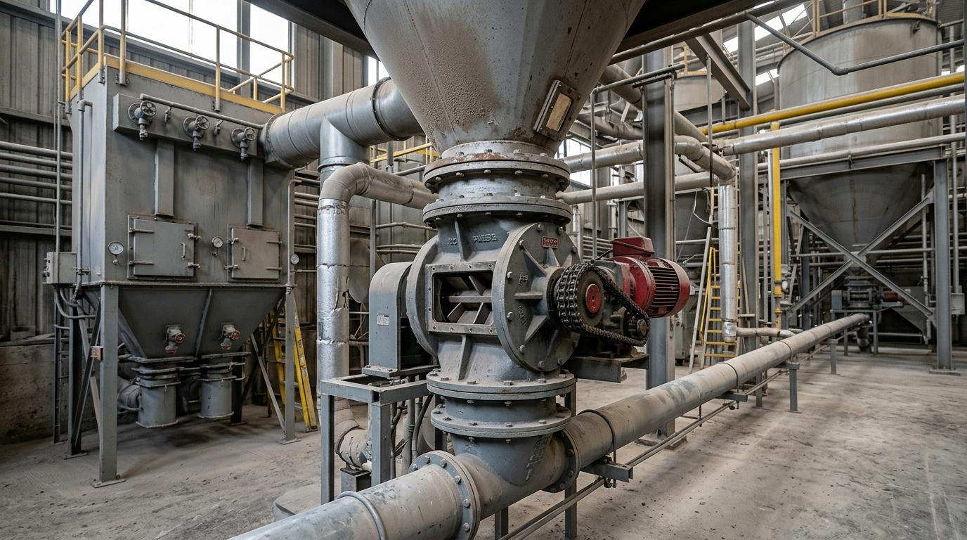
The importance of an air lock rotary valve in pneumatic conveying comes down to two jobs: it meters material and preserves the pressure differential the system needs to move product and control dust. If leakage rises because of poor clearances, wear, or the wrong design, conveying capacity drops, energy use climbs, and dust control performance suffers.
A rotary airlock valve (also called a rotary valve or airlock feeder) does two jobs at once: it meters bulk material from a hopper, silo, or dust collector into the next process while holding the pressure differential the system needs to run.
Without it, air leaks, conveying velocity drops, dust re-entrains, and energy use climbs. In pneumatic conveying it is the interface between atmospheric pressure and the pressurized or vacuum line, often working alongside routing components such as a diverter valve when material has to be directed through different paths. In dust collection it is the continuous discharge device that keeps the collector under vacuum without shutting the fan down.
This post covers how the valve works, why the seal matters more than most people realize, the practical limits of leakage, and what happens when the wrong valve is specified.
What a rotary airlock valve actually does
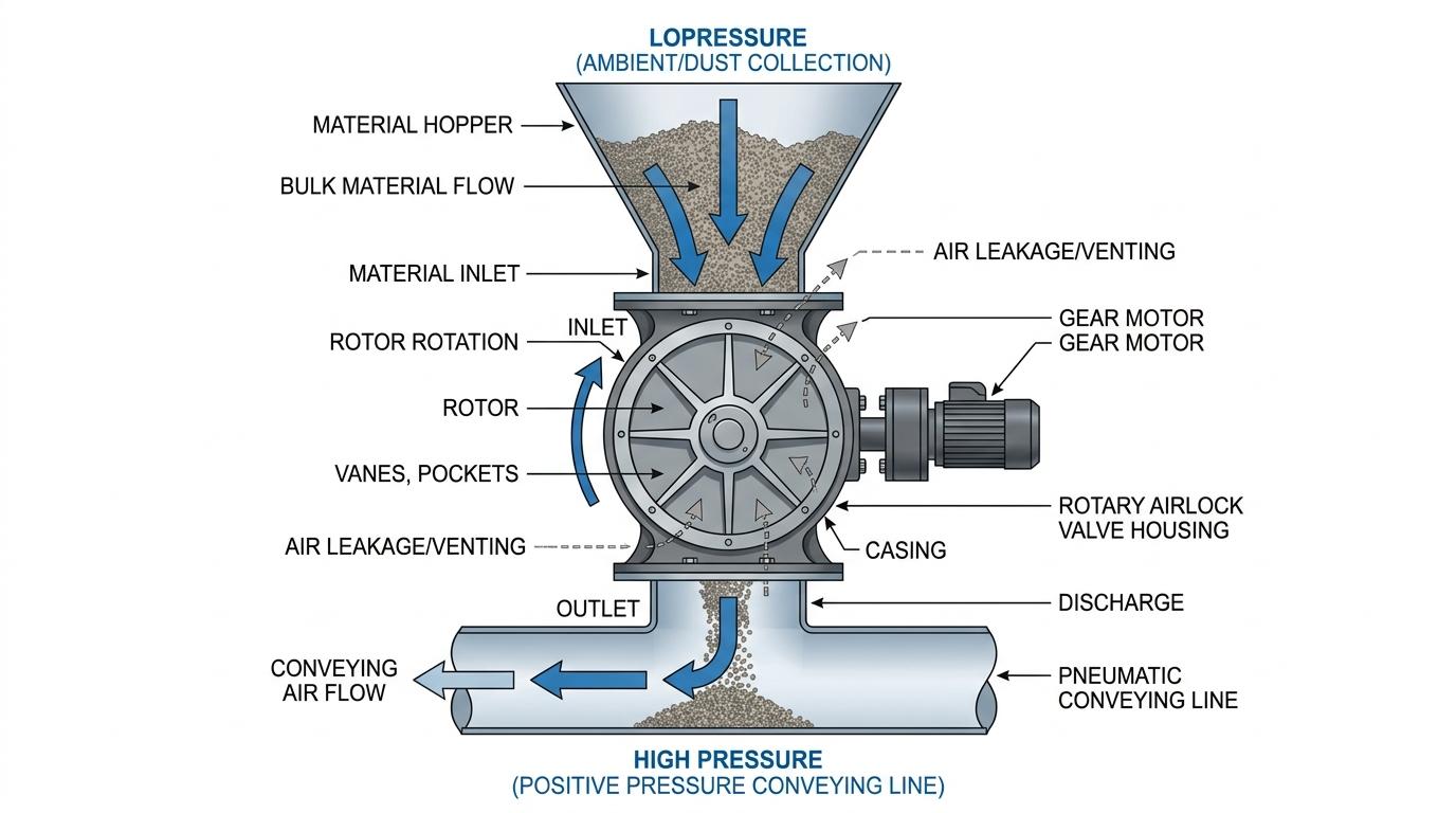
Material drops by gravity into the pockets formed by the rotor vanes. The rotor turns slowly (typically 10–25 rpm). Each pocket carries a fixed volume of material around the housing and dumps it at the bottom outlet. While that is happening, the tight clearance between the vane tips and the housing body limits air movement from the high-pressure side to the low-pressure side.
Typical clearances are 0.004 to 0.006 inches about the thickness of a coarse hair. That gap is small enough to cut leakage dramatically, yet large enough for the rotor to turn without binding. The valve is never a perfect seal; some leakage always occurs. The design goal is to keep that leakage low enough that system pressure and conveying velocity stay inside the design range.
Three common roles appear in plants:
Airlock only : discharge from a dust collector or receiver while holding vacuum or pressure.
Feeder only : controlled volumetric feed under gravity or low differential.
Combined airlock + feeder : the most common use in dilute-phase pneumatic conveying, where material is introduced into a pressurized or vacuum line.
The valve looks simple, but its effect on system pressure, energy use, and dust control is significant. If you need a quick technical reference while comparing options or reviewing a plant requirement, keep the spec sheet handy for the key selection details.
Why the air seal is non-negotiable in pneumatic conveying
Pneumatic systems live or die by pressure differential. In a positive-pressure dilute-phase line the blower pushes air and material. In a vacuum line the fan pulls. Either way, the rotary airlock sits at the boundary.
If too much conveying air leaks upward through the valve into the feed hopper:
Available pressure or vacuum at the conveying line falls.
Air velocity drops.
Material falls out of suspension and forms plugs.
The blower or fan works harder (or has to be oversized) to compensate.
Energy cost rises and capacity falls below design.
Leakage also carries fine dust back into the hopper above, re-suspending collected material and degrading filter efficiency. In dust collection systems the same mechanism destroys the pressure balance the collector needs to capture dust at the hoods. Without a working airlock, the system either loses suction or allows dust to escape into the plant.
The valve’s ability to maintain that differential is what distinguishes it from a simple gravity chute, a slide gate used mainly for shut-off, or a flow control gate chosen for controlled discharge in other parts of the handling line.
How leakage happens and how much is normal
Leakage has two components:
Static leakage through the fixed clearances between rotor tips, sides, and housing.
Dynamic leakage the volume of pressurized air trapped in each empty pocket as it rotates back toward the inlet.
Higher differential pressure, higher rotor speed, and worn clearances all increase leakage. Abrasive materials wear the tips and housing, enlarging the gap over time. Sticky or fine powders can pack and change the effective clearance.
Proper venting (a body vent or vented transition) is usually required on pressure systems so that leakage air is directed away from the feed material rather than fluidizing it and reducing pocket fill. In fine-powder systems where air-assisted flow matters, related equipment such as an air slide assembly may also support smoother downstream movement. If you are diagnosing venting, dust recirculation, or material flow issues, review our Problems & Solutions page for related plant-side challenges. Without venting, light powders may refuse to enter the pockets at all.
Dust control and safety benefits
In a dust collector the rotary airlock lets collected material discharge continuously without breaking the vacuum. Operators do not have to shut the system down to empty the hopper. That keeps the collector online and reduces the chance of dust escaping into the work area, which aligns with established NIOSH dust-control guidance for industrial environments.
Where combustible dust is present, a properly designed rotary airlock can also serve as a flame-isolation device. OSHA guidance on combustible dust and the broader NFPA combustible dust standard framework both underline why dust containment, ignition control, and isolation matter in plant design. The same tight clearances that limit air leakage also help support safer operation when the valve is correctly specified.
Practical limits and common failure modes
Clearance growth from abrasion is the usual long-term problem. Once the gap opens, leakage rises, capacity drops, and the cycle accelerates.
Undersized valves run too fast, reducing fill efficiency and increasing wear.
Wrong rotor style (open vs. closed-end, number of vanes) for the material and pressure differential shortens life and raises leakage.
Lack of venting on pressure systems fluidizes the feed and starves the line.
Thermal expansion on hot materials can close clearances and seize the rotor if the valve was not designed for the temperature.
A plain belt conveyor has a clear 20-degree practical limit. A rotary airlock has no single “maximum pressure” number that applies to every application, but most standard units are rated around 15 psig differential. Higher differentials demand tighter clearances, more vanes, heavier construction, and more frequent inspection. Leakage also has an operating-cost impact because poor pressure control makes air systems work harder, a point that lines up with U.S. Department of Energy guidance on compressed-air system performance.
Quick application guide: Use this table to match the duty with the design priority that matters most.
Application | What the valve must do | Main design priority |
|---|---|---|
Dust collector discharge | Continuously discharge collected dust while holding vacuum | Low leakage and stable sealing clearance |
Positive-pressure dilute-phase conveying | Meter bulk material into a pressurized conveying line | Good venting, controlled leakage, and reliable pocket fill |
Vacuum conveying feed point | Maintain vacuum while introducing material into the system | Air seal performance and wear control |
Abrasive bulk solids | Resist rapid clearance growth under continuous wear | Wear-resistant construction and easier maintenance access |
Sticky or cohesive powders | Avoid build-up, bridging, and poor discharge consistency | Rotor style, surface finish, and clean-out access |
When a rotary airlock is the right (or wrong) choice
It is the default solution for continuous metering into dilute-phase pneumatic conveying and for continuous discharge from dust collectors and receivers. It is compact, relatively simple, and well understood in industries where bulk material handling performance directly affects uptime. In layouts that call for a different feed style, screw conveyors may be considered for controlled material transfer before product enters the next stage of the system.
It is not ideal for:
Highly abrasive materials at high differentials (wear becomes the dominant cost).
Sticky or cohesive materials that pack in the pockets (blow-through designs or special coatings help, but alternatives may be better).
Applications that need a near-perfect seal (double-dump or specialized isolation valves can outperform it on absolute leakage).
If you are weighing leakage risk, wear rate, or the right valve configuration for your plant, a technical review can save time before you commit to a standard unit that may not suit the duty. A quick discussion with an engineer can help you match the application, pressure differential, and material behavior to the right solution, and our engineering services page outlines the support available across design, troubleshooting, and execution.
Key takeaways
The rotary airlock valve meters material and maintains the pressure differential that pneumatic conveying and dust collection systems require.
Tight clearances (0.004–0.006 in) cut leakage enough for the system to work; they never eliminate it.
Excess leakage reduces conveying capacity, raises energy use, re-entrains dust, and can compromise safety isolation.
Venting, correct rotor design, and material-matched clearances determine whether the valve performs for years or becomes a recurring maintenance item.
Specify from the material and differential first; the rest of the system follows.
Frequently asked questions
It is the component that lets material enter or leave the conveying line while holding the pressure or vacuum the system needs. Without an effective airlock, air leaks, velocity falls, and the line plugs or loses capacity.
In dust collectors it allows continuous discharge without breaking the vacuum seal. That keeps the collector operating at design airflow and prevents collected dust from escaping back into the plant.
No. They are precision airlocks, not absolute seals. Some leakage is inherent in the clearance required for rotation. The design goal is controlled, low leakage that the system can tolerate.
0.004 to 0.006 inches on most industrial valves. Tighter clearances reduce leakage but increase the risk of binding and wear, especially with temperature changes or abrasive materials.
When the material is highly abrasive, sticky, or the differential pressure is extreme, or when near-zero leakage is mandatory. Double-dump valves, specialized isolation devices, or changes to the system layout may perform better.
Yes. Higher speed reduces pocket fill efficiency, increases dynamic leakage, and accelerates wear. Most applications run well below 25 rpm; the exact speed is set by the required throughput and the valve’s volumetric capacity.