
Conveyor Idler Selection Guide: How to Choose the Right Idler for Your Application

Vijay Baid
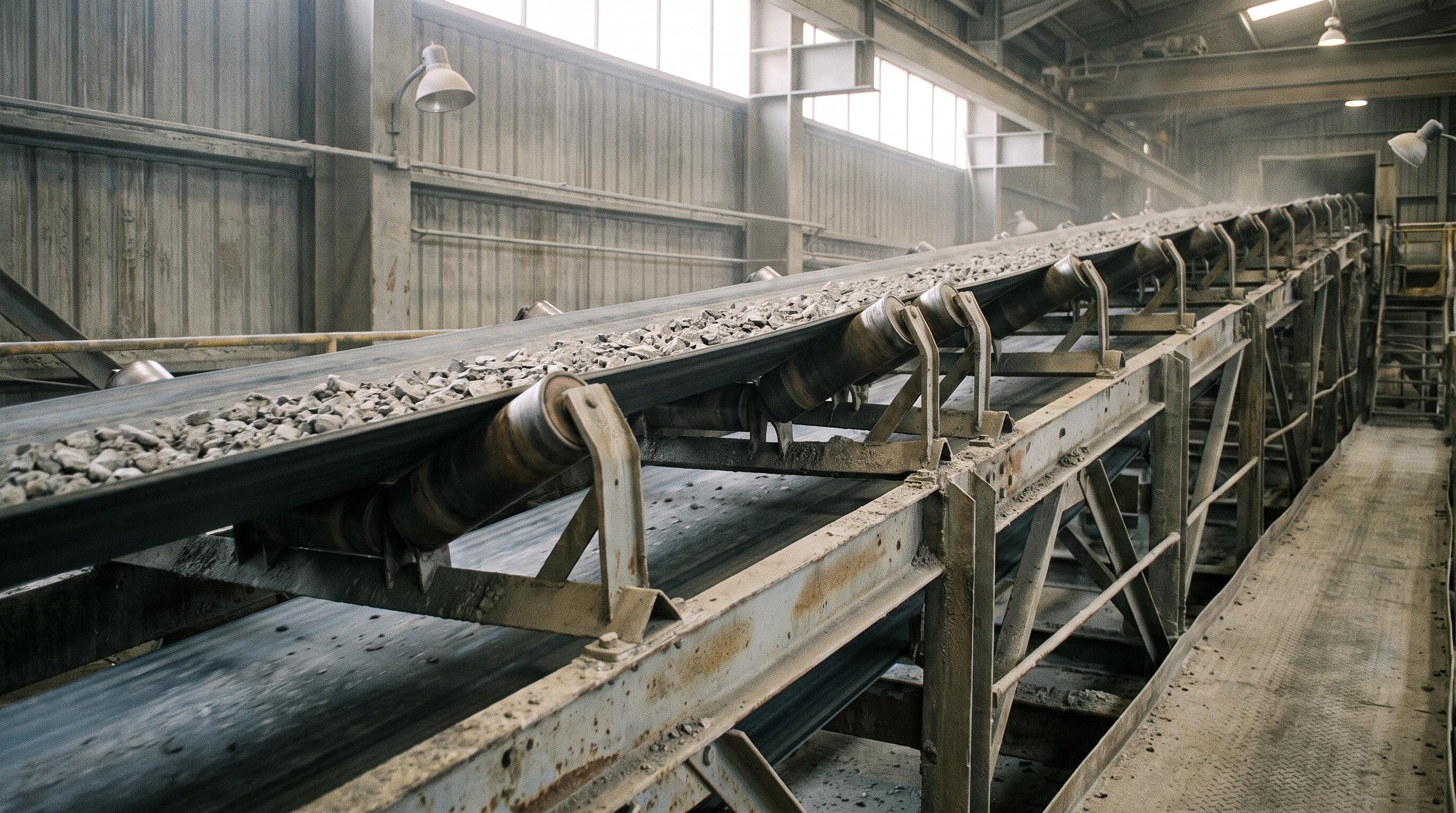
Selecting the right conveyor idler is more than choosing a roller that fits the belt width. Engineers must evaluate operating load, conveyor speed, material characteristics, duty class, bearing life, and environmental conditions before specifying an idler.
A poorly selected idler can lead to premature bearing failure, shaft deflection, excessive belt wear, and unnecessary maintenance costs.
Choosing the right conveyor idler is an engineering task. Belt width alone is not enough. You also need to check material load, impact forces, bearing life, and shell wear. If you skip those checks, the idler can fail early.
The Engineering Selection Workflow: Beyond Catalog Lookups
To eliminate premature component failure, follow this structured calculation workflow:
1. Gather Operating Parameters (TPH, Speed, Width)
2. Calculate Total Equivalent Idler Load (PL)
3. Determine Roller RPM & Select Diameter
4. Select CEMA / ISO Duty Class & Shaft Size
5. Verify Bearing L10 Fatigue Life
6. Specify Multi-Stage Seals & Shell Material
Step-by-Step Idler Selection Calculations
Step 0: Identify the Conveyor Zone
Loading zone → use the loading-zone idler configuration.
Carrying zone → use the carrying-zone configuration.
Return zone → use the return-zone configuration.
Step 1: Calculate Total Equivalent Idler Load (PL)
The main structural check is the total vertical load, PL, on one idler set. This value includes material load, belt weight, idler spacing, and dynamic service factors.
First, calculate the material payload per linear foot, Wₘ:
Wm = 100 x T / 3 x V
Where:
Wₘ = material load per foot, in lb/ft
T = material feed rate, in STPH
V = conveyor belt speed, in ft/min
Next, determine total load per idler set (PL):
PL= (Wₘ + Wb) x Si x Ki
Where:
Wb = belt weight per linear foot, in lb/ft
Sᵢ = idler frame spacing, in ft
Kᵢ = dynamic overload and environmental factor, typically 1.0 ≤ Kᵢ ≤ 1.5
Load Distribution Note: On a standard 3-roll troughing set, the center roller bears 60% to 70% of the total calculated load (PL). Always size the center roller bearing and shaft against this concentrated load profile.
Step 2: Select Roller Diameter Based on Operating Speed
High roller speed creates heat in the bearings. It also breaks down grease faster. Use belt speed, V, and roller diameter, D, to calculate RPM.
Roller RPM = 12 x V / π x D = 3.819 x V / D
Where:
V = belt speed, in ft/min
D = roller outside diameter, in in
Speed Limiting Rules
Keep rotational speeds within safe mechanical limits to maximize bearing grease life:
Continuous Mining / Heavy Power Duty: Target ≤ 600 RPM
Standard Industrial Duty: Target ≤ 800 RPM
If a 127 mm (5.0 in) roller exceeds 600 RPM at the required belt speed, move up one size. Use a 152 mm (6.0 in) or 178 mm (7.0 in) roller to reduce rotational speed.
Belt Speed (m/s) | Belt Speed (ft/min) | Min. Recommended Roll Diameter (mm) | Min. Recommended Roll Diameter (in) |
|---|---|---|---|
V < 2.5 m/s | V < 500 ft/min | 127 mm | 5.0 in |
2.5 - 4.5 m/s | 500 - 900 ft/min | 152 mm | 6.0 in |
V > 4.5 m/s | V > 900 ft/min | ≥ 178 mm | ≥ 7.0 in |
Step 3: Select the Correct CEMA Duty Class Based on Calculated Load
Compare your calculated load (PL) against standard duty ratings defined by the Conveyor Equipment Manufacturers Association (CEMA) and international standard ISO 1536.
Class B | Light Duty | (Ag-lime, Sand, Fine Aggregate) |
Class C | Medium Duty | (Crushed Stone, Coal, Light Ores) |
Class D | Heavy Duty | (Heavy Ore, Coal, Cement Clinker, Limestone) |
Class E | Severe Duty | (High-TPH Iron Ore, Hard Rock Mining) |
Class F | Extra-Heavy | (Overland Mining Loops, > 10,000 TPH Systems) |
Shaft and Bearing Specs by CEMA Class
CEMA Class | Standard Shaft Diameter | Primary Bearing Type | Application Profile |
|---|---|---|---|
CEMA C | 20 mm (0.787 in) | Deep-groove ball bearings | Light-to-medium bulk handling |
CEMA D | 25 mm (0.984 in) | Deep-groove ball / tapered roller | High-speed coal, clinker, limestone |
CEMA E | 30–40 mm (1.18–1.57 in) | Heavy tapered / spherical roller | Primary ore crushing, heavy drop zones |
CEMA F | ≥ 40 mm (≥ 1.57 in) | Precision tapered roller | High-velocity overland extraction |
Download our complete idler spec sheet to instantly cross-reference CEMA classifications, roller wall thicknesses, bearing part numbers, and dimensional standards.
Step 4: Verify Bearing Fatigue Life (L₁₀)
Bearing life, L10, shows how long most bearings should last under load. In practice, 90% of identical bearings should meet or exceed this life before fatigue failure starts.
L₁₀ = (16,666/N) × (C/P)ᵖ
Where:
N = roller rotational speed, in RPM
C = basic dynamic load rating of the bearing, in N or lbf
P = dynamic equivalent radial bearing load, in N or lbf
p = 3 for ball bearings and 10/3 for roller bearings
For industrial plant operations, target L₁₀ ≥ 60,000 h for standard service and L₁₀ ≥ 100,000 h for continuous power-plant and mining duty.
Step 5: Specify Seal Design for the Operating Environment
Sealing Systems
Abrasive Dust (Cement, Clinker, Fly Ash): Specify grease-filled Triple-Labyrinth Seals to create a tortuous path that blocks fine dust from reaching bearing races.
High Moisture & Washdown Zones: Use contact lip seals with external deflector flinger rings.
High Thermal Exposure (Hot Sinter, Calcined Ore): Specify high-temperature fluoropolymer seals (Viton/FKM) and synthetic grease.
Shell Material Selection
ERW steel tubing: standard choice for non-corrosive, general bulk materials.
Heavy-wall steel (6–8 mm): essential for high-abrasion ores to prevent premature shell wall thinning.
HDPE / polyurethane composites: ideal for sticky materials prone to carryback corrosion, or where strict noise abatement below 70 dBA is required under OSHA Conveyor Safety Regulations.
Real-World Engineering Sizing Example
The following example demonstrates how the complete selection workflow is applied in practice, from calculating conveyor loads to selecting the appropriate CEMA class and roller diameter.
Step-by-Step Resolution
Material load, Wₘ: Wₘ = (100 × 2,500) / (3 × 750) = 111.1 lb/ft.
Total idler load, PL, at Sᵢ = 4.0 ft and Kᵢ = 1.15: Pₗ = (111.1 + 22) × 4.0 × 1.15 = 612.26 lb/frame.
Center-roll peak load: 0.65 × 612.26 = 397.97 lbf.
RPM analysis for a 5.0 in roller: (3.819 × 750) / 5.0 ≈ 573 RPM. This is a high-speed condition and is more prone to grease degradation.
RPM analysis for a 6.0 in roller (152 mm): (3.819 × 750) / 6.0 ≈ 477 RPM. This is a more stable operating range.
Selection result: a center-roll load of approximately 398 lbf on a 48 in belt exceeds CEMA C limits. A CEMA D6 idler with a 152 mm shell and 25 mm shaft is a safer fit. Multi-stage labyrinth seals also push calculated L₁₀ life well above 100,000 h.
When you add new idlers to an automated line, check the full transfer path. Make sure the upstream transfer point and the downstream Screw Conveyor feed gate work together. That helps keep flow balanced and reduces spillage.
Need help selecting the right conveyor idler for your application? Our engineering team can review your conveyor loading conditions, calculate the required CEMA duty class, verify bearing life, and recommend the most suitable idler specification for long-term reliability.
Field Experience: During a plant audit at a steel mill, the team said they were replacing carrying rollers every four months. The conveyor was 1,200 mm wide and ran at 3.8 m/s. It carried heavy iron ore. The root cause was clear. The original design used light CEMA C rollers with 20 mm shafts. Under high point loads, those shafts bent slightly. That small bend misaligned the bearing races. The rollers then overheated and failed early. Once a roller seized, the moving belt dragged across the shell. That damaged the belt cover. We replaced the line with CEMA E idler frames. The new design used 30 mm solid shafts, 152 mm heavy-wall tubes, and multi-labyrinth grease seals. After that, shaft deflection dropped sharply. The conveyor then ran for more than two years without an unscheduled shutdown.
Final Key Takeaways
Calculate, don’t guess: idler selection requires calculating total dynamic load (Pₗ), center-roll distribution, and bearing L₁₀ life. Never select idlers from belt width alone.
Control rotational speed: increasing roller diameter from 127 mm to 152 mm reduces RPM, lowers bearing temperature, and extends grease life.
Prevent shaft deflection: ensure the selected CEMA duty class (C, D, E, or F) provides sufficient shaft diameter to prevent micro-flexing under peak load.
Match seals to the environment: use triple-labyrinth seals for dusty cement and clinker service, and contact lip seals with external deflectors for wet washdown zones.
This guide focuses on engineering selection and specification. If you need help understanding the functions of different conveyor idler configurations, read our Complete Guide to Conveyor Idler Types and Selection.
Frequently Asked Questions (FAQ)
The main differences are shaft diameter, bearing rating, and overall load capacity. CEMA C idlers typically use 20 mm (0.787 in) shafts with smaller ball bearings suited to medium-duty bulk handling. CEMA D idlers use heavier 25 mm (0.984 in) shafts, larger bearings, and thicker roll walls designed for higher loads, higher speeds, and harsher operating conditions.
Larger roller diameters reduce rotational speed and rolling resistance. Lower RPM reduces bearing friction and heat buildup. The larger surface also distributes load more evenly. That lowers belt indentation resistance and overall drive motor power draw.
When an idler shaft bends under heavy load, it misaligns the inner and outer bearing races. Even a small angular deflection creates uneven stress on the rolling elements. That accelerates fatigue, breaks down lubrication, and can lead to seizure.
For standard continuous processing lines, specify a minimum L₁₀ life of 60,000 h. For critical high-volume mining, power-plant, or port-loading applications, specify L₁₀ ≥ 100,000 h.