
Conveyor Pulley Types: Head, Tail, Snub, Bend & Drive Pulleys Explained

Vijay Baid
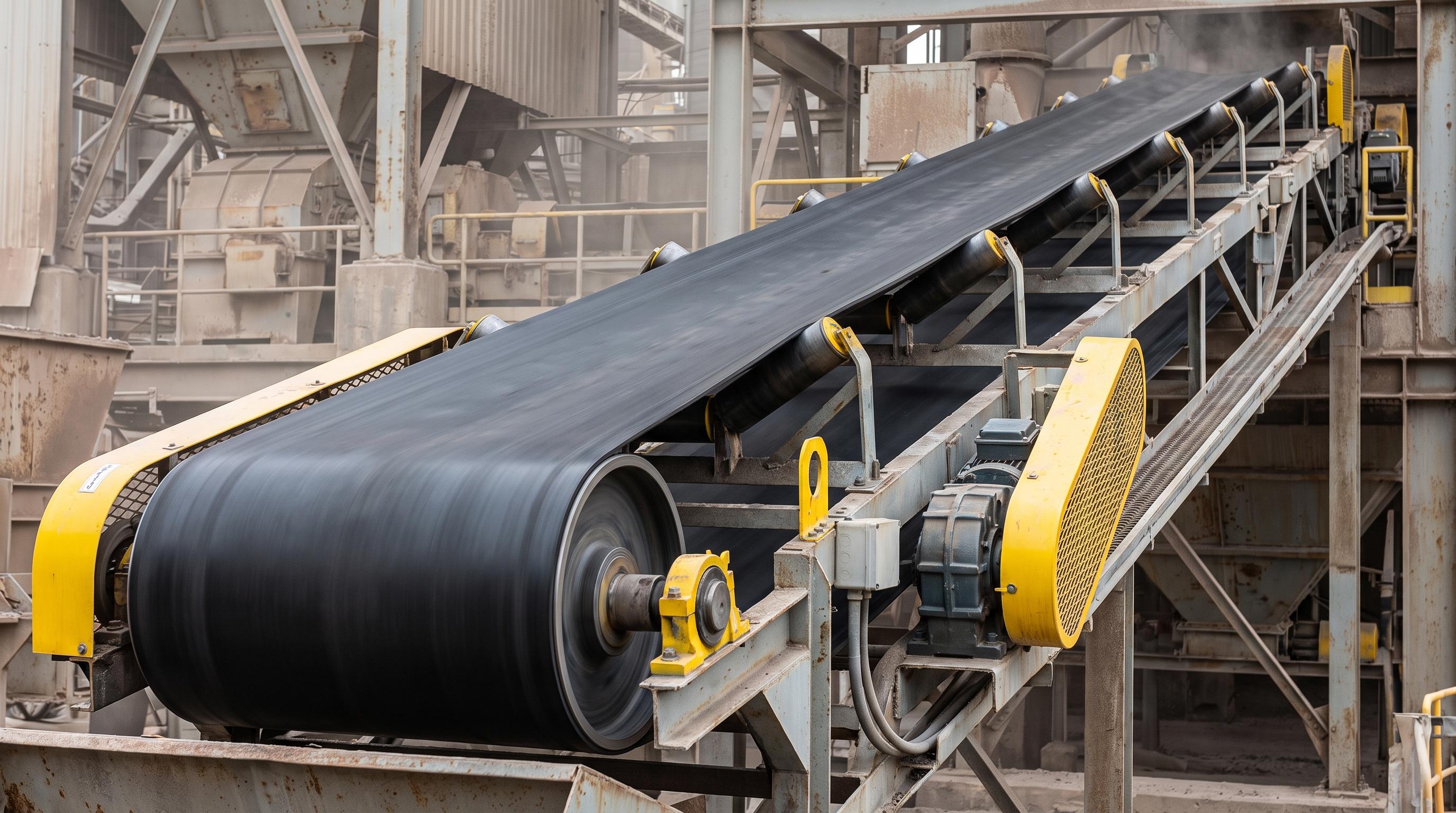
Each conveyor pulley has a specific job. Head or drive pulleys transmit torque. Tail pulleys return and align the belt. Snub pulleys increase wrap angle and improve traction. Bend pulleys change belt direction. Take-up pulleys maintain tension. Motorized pulleys combine the motor and pulley in one compact unit. Good pulley selection depends on duty, lagging, wrap angle, shaft strength, bearing life, and site conditions. When these parts match the application, plants reduce belt slip, uneven wear, shaft failures, and unplanned shutdowns.
In bulk material handling systems, the conveyor belt is central to production. But the belt cannot move, track, or hold proper tension without the pulleys at the ends and transition points. These pulleys are not simple steel drums. They are engineered parts built to handle high torque, belt tension, and continuous material flow in cement plants, steel mills, mines, and power stations.
Using the wrong pulley type, poor lagging, or weak load calculations can quickly cause belt tracking problems, shaft fatigue, and costly shutdowns. Safety teams must also make sure all rotating drums are properly guarded to reduce the risk of worker injury, in line with machine guarding guidance.
To keep conveyor reliability above 95%, engineering teams need clear design standards. Using CEMA guidance and IS 8531 helps reduce bearing seizure, shell wear, and avoidable failures. It also improves total cost of ownership over the life of the system.
The Anatomy of a Conveyor Pulley Loop
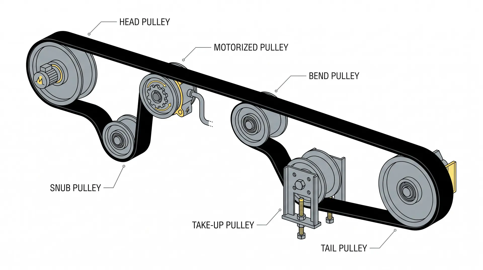
To design a reliable conveyor layout, you need to know where each pulley sits and what it does in the carry and return path of the belt conveyor.
1. Head/Drive Pulley: The Power Transmission Component
The drive pulley provides the mechanical power needed to move the conveyor belt and its material payload. Placed at the discharge end, it receives torque from the drive motor through a gearbox and transmits this force to the belt via friction.
Primary Duty: Transmitting high rotational torque from the drive motor into linear belt movement without slipping.
Operating Profile: To prevent the belt from slipping under heavy loads, drive pulleys are wrapped in high-friction pulley lagging. This lagging typically features vulcanized rubber or embedded ceramic tiles with grooved patterns (such as diamond or herringbone) that shed water and fine particles.
Structural Design: Because drive drums handle the highest mechanical stress in the system, they are built with thick steel shells, heavy end discs, and solid shafts secured with keyless locking assemblies. UGES manufactures these pulleys using IS 2062 Gr. E250 mild steel plates.
2. Tail Pulley: Belt Return and Alignment
The tail pulley sits at the feed end of the conveyor. It turns the empty return belt and sends it back into the loaded carrying run.
Primary Duty: Guiding the return belt back into the loading zone and maintaining proper system geometry.
Operating Profile: While it does not transmit power, the tail pulley plays a critical role in belt tracking. Tail pulleys are typically smaller in diameter than drive pulleys since they experience lower belt tension. Standard diameters range from 250 mm to 630 mm for most industrial applications.
Self-Cleaning Wing Designs: Because the tail pulley sits directly below material loading chutes, it is prone to trapping spilled rocks or stray material between its face and the inner belt cover. To prevent this material from crushing the belt, engineers specify winged self-cleaning tail pulleys. These pulleys feature steel slats arranged in a V-shape or spiral pattern that physically throw escaping material out to the sides of the conveyor.
3. Snub Pulley: Enhancing Drive Traction
A snub pulley is positioned close to the primary drive drum along the return path of the belt.
Primary Duty: Changing the belt's path to increase its wrap angle around the drive pulley.
Operating Profile: By deflecting the belt path, a snub pulley increases the wrap angle (θ) around the drive drum from a standard 180° up to 210° or 220°. This increased wrap angle provides more surface contact, allowing the drive drum to transmit more power without slipping.
Engineering Impact: Squeezing more traction out of the drive drum via a snub pulley lets you run lower overall system tensions, which extends the service life of your conveyor belt and carrying Conveyor Idlers.
4. Bend Pulley: Direction Change Elements
Bend pulleys change the direction of the belt path, either vertically or horizontally, without transmitting power. They help route the belt through the conveyor structure where space or layout demands a change in direction.
Primary Duty: Reroute the belt path around plant obstacles or toward internal take-up systems.
Operating Profile: They are used in convex and concave curve sections and where conveyors must navigate around processing equipment. Bend pulley diameters typically range from 315 mm to 800 mm, selected based on belt rating and bend geometry.
Stress Factor: While they do not transmit drive torque, bend pulleys operate in high-tension zones, meaning they require solid end discs and rigid structural shafts to handle the combined forces of belt tension and centrifugal material forces.
5. Take-up Pulley: Tension Management
Take-up pulleys keep belt tension at the right level across the conveyor. They compensate for belt stretch caused by load changes, temperature shifts, and splice movement over time.
Gravity Take-up Systems: Employ a weighted pulley that moves vertically inside a tower structure to maintain constant tension. This configuration is common in long overland conveyors where consistent tension is critical. The take-up weight is calculated based on required belt tension, typically 3-5% of the maximum belt tension for fabric belts.
Screw Take-up Systems: Use a threaded adjustment mechanism to position the pulley and set belt tension. This compact design is preferred for short to medium-length conveyors and indoor installations where space is limited. Manual adjustment is required periodically to compensate for permanent belt elongation.
6. Motorized Pulley: Integrated Drive Unit
A motorized pulley has the electric motor, gearbox, and bearings built inside the steel drum. This gives you a compact drive unit with fewer exposed parts. For a practical example of how this format is used in industry, see this motorized pulley reference.
Primary Duty: Providing a compact, self-contained drive mechanism for space-constrained production facilities.
Operating Profile: By eliminating external motors, gearboxes, fluid couplings, and drive chains, motorized pulleys reduce the overall physical footprint of the head terminal. Because all moving components operate within a sealed oil bath, they are highly protected from abrasive external dust.
Application Limit: While highly efficient and easy to wash down, they feature limited heat dissipation compared to externally mounted gearboxes. They require careful oil monitoring when deployed on high-temperature clinker or hot sinter lines.
Technical Comparison
Choosing the right pulley means matching each drum design to the loads at its position in the conveyor loop. The comparison below summarizes the main differences using IS 8531 and CEMA guidance.
Pulley Type | Primary Loop Location | Torque Transmitted | Typical Lagging Configuration | CEMA Duty Class | Main Engineering Focus |
Drive Pulley | Head or Tail Terminal | High Rotational Torque | Diamond/Herringbone Rubber or Ceramic | Standard / Heavy Duty | Torque transmission, shell thickness, grip optimization |
Head Pulley | Material Discharge Point | None (unless acting as Drive) | Plain Rubber or Ceramic Lagging | Standard / Heavy Duty | Belt tracking, scraper interface, material clearance |
Tail Pulley | Material Loading Terminal | None | Winged Self-Cleaning or Plain Steel | Standard Duty | Spillage removal, take-up alignment, impact resistance |
Snub Pulley | Downstream from Drive Drum | None | Plain Rubber or Plain Smooth Steel | Standard / Heavy Duty | High bending stress, bearing life, wrap angle expansion |
Bend Pulley | Gravity Take-Up / Reroute Points | None | Plain Smooth Steel or Plain Rubber | Standard / Heavy Duty | Radial load capacity, structural shaft stiffness |
Take-up Pulley | Return side (Variable position) | None | Plain Smooth Steel | Standard Duty | Dynamic weight tracking, bearing alignment |
Motorized Pulley | Head Discharge Terminal | Internal Motor Torque | Grooved Vulcanized Rubber | Specialized Drive | Internal thermal dissipation, planetary gear tolerances |
Access complete engineering datasheets, dimensional drawings, and selection guides for heavy-duty conveyor pulleys compliant with CEMA and IS 8531 requirements.
Selection Factors: Engineering Your Pulley Layout
To specify the correct industrial pulley from a manufacturer's catalog, engineering teams must calculate three critical design parameters:
1. Determining the Wrap Angle and Belt Traction
The amount of force a drive pulley can transmit into a belt without slipping is determined by the Euler-Eytelwein equation:
T1 / T2 ≤ eμθ
Where:
T1 = Tight-side belt tension (N)
T2 = Slack-side belt tension (N)
μ= Coefficient of friction between the pulley surface and the belt cover
θ = Belt wrap angle around the pulley drum (radians)
Consider a drive pulley with rubber lagging ( μ= 0.35) and a wrap angle of 200° (3.49 radians). The tension ratio is:
T1 / T2 = e0.35 × 3.49 = e1.22 = 3.39
This means the tight-side tension can be 3.39 times the slack-side tension before the belt starts to slip. If a snub pulley raises the wrap angle to 220° (3.84 radians), the ratio increases again:
T1 / T2 = e0.35 × 3.84 = e1.34 = 3.82
This demonstrates how a snub pulley directly increases the power transmission capacity of your conveyor drive. All tension calculations and equipment ratings should be validated against the mechanical standards maintained by the CEMA Framework.
2. Choosing the Right Pulley Lagging
The surface covering of your pulley shell directly impacts how well the conveyor tracks and how long the belt lasts:
Plain Rubber (8-12 mm): Used for general-purpose applications handling dry, non-abrasive materials. It offers a baseline friction coefficient of 0.35 to 0.40 per DIN 22101 but can wear rapidly on high-tension drives.
Diamond/Herringbone Groove Rubber (10-15 mm): Features molded grooves that channel water and fine dust away from the belt surface. This makes it ideal for outdoor drive pulleys operating in wet conditions or inclined runs.
Ceramic Lagging (12-20 mm): Features high-hardness aluminum oxide tiles embedded in a durable rubber backing. Ceramic lagging provides an exceptional friction coefficient (0.45 to 0.55), making it the top choice for high-tonnage lines operating in wet, muddy conditions where belt tensions exceed 100 kN.
3. Shaft and Bearing Design Criteria
The pulley shaft must handle three main loads: bending from belt tension, torsion from power transmission, and fatigue from repeated cycles. The shaft material should match the required torque and duty level, in line with BIS standards such as IS 1570:
C40 Grade (EN8 equivalent): Medium carbon steel for light-duty applications, pulleys up to 630 mm diameter, and belt tensions below 30 kN.
40Cr4 Grade (EN19 equivalent): Chromium steel for medium-duty drives, pulleys from 630 mm to 1000 mm, and belt tensions between 30 kN and 80 kN.
40NiCr4Mo2 Grade (EN24 equivalent): High-strength alloy steel for heavy-duty applications, pulleys above 1000 mm diameter, and belt tensions exceeding 80 kN.
Bearing selection starts with L10 life calculations under ISO 281. A common target is at least 50,000 hours. Heavy-duty spherical roller bearings in the 22 and 23 series are widely used because they carry high radial loads and tolerate small shaft misalignment.
Common Design and Maintenance Mistakes
Under-Specifying Shell Thickness: Sizing a pulley based solely on its diameter while ignoring peak belt tension is a common engineering oversight. Under heavy load, an under-specified shell will flex, causing the welded end discs to crack near the hub and lead to a complete structural failure.
Omitting a V-Plow Scraper Ahead of the Tail Drum: Running a standard smooth steel drum pulley at the tail terminal without a V-plow scraper is a major risk. Any stray rocks that fall onto the return belt will get dragged directly between the pulley face and the moving rubber, puncturing the belt carcass and denting the pulley shell.
Keyed Shafts in High-Torque Zones: Legacy pulleys often relied on keyed shafts to transmit torque. However, under continuous cyclic loading, these keyways frequently develop stress cracks that can lead to sudden shaft failure. Modern heavy-duty pulleys use keyless, multi-wedge locking assemblies to distribute torque evenly.
From the Field: A high-capacity cement plant was facing repeated drive shaft failures on a primary limestone reclaim conveyor. The line handled heavy material on a steep incline and drew high motor power. Every few months, the main drive shaft cracked near the welded end disc and failed, stopping the entire line.
Our audit showed two main problems. The conveyor still used an older keyed shaft with C40 steel, and the keyway was concentrating stress under constant torque changes. At the same time, the smooth rubber lagging slipped during monsoon conditions. That created sharp torque spikes each time the belt regained grip.
We fixed the problem by replacing the failed drum with a heavy-duty pulley from United Global Engineering Solutions. The new drum used a 40NiCr4Mo2 alloy steel shaft, a keyless locking assembly, and high-traction ceramic lagging. The keyless design spread torque more evenly across the shaft, and the ceramic surface stopped belt slip in wet conditions. After the retrofit, the drum ran for more than four years without a shaft failure or tracking issue.
If you are experiencing premature pulley failures, shaft fatigue, or belt slippage along your critical handling lines, our technical support specialists can help. Contact us directly to review your system's dynamic loads and receive a tailored structural evaluation.
Final Takeaway
An efficient conveyor system depends on matching the pulley design to your material and process conditions. Use high-traction drive pulleys for power transmission, self-cleaning tail pulleys to control trapped material, and properly placed snub and bend pulleys to manage belt path and tension.
Your pulley layout should also work smoothly with the rest of the material handling line. This includes downstream equipment such as belt conveyors, screw conveyors, flow control gates, and diverter valves. When these systems are aligned, plants avoid shutdowns and keep material moving safely.
Frequently Asked Questions (FAQ)
A drive pulley is coupled directly to a motor and gearbox reducer to provide the rotational force that moves the belt. A head pulley simply refers to the drum positioned at the discharge terminal of the conveyor frame. On most standard conveyor setups, the head pulley serves as the drive drum, but some long systems utilize mid-driven or tail-driven configurations.
You should install a winged tail pulley whenever the rear terminal sits directly below an open material transfer zone or a feed chute prone to spillage. The open steel slats throw escaping material out to the sides, preventing rocks from getting trapped under the belt and causing severe carcass damage.
Ceramic lagging utilizes high-hardness tiles embedded in a rubber base to deliver more than twice the gripping friction of standard rubber. This extra grip completely eliminates belt slippage on high-torque drives, heavy inclines, and wet, muddy operations, providing 3 to 5 times the service life of conventional rubber lagging.
Uneven shell wear is usually caused by material carryback buildup on the drum face or an improperly aligned belt scraper. If a scraper applies uneven pressure across the belt, fine abrasive dust will pass through, creating a grinding paste that rapidly wears down localized zones of the pulley lagging.
Expanding the belt wrap angle (typically by positioning an adjustable snub pulley close to the drive drum) increases surface contact and traction. This extra grip allows the drive system to move the identical material payload with lower slack-side tension, reducing the structural strain on your belt plies and extending the service life of your internal bearings.
An integrated motorized pulley houses the electric motor, planetary gearbox, and bearing array completely inside the sealed pulley shell. This eliminates external drive chains, couplings, and pillow blocks, saving massive amounts of physical floor space and protecting the drive components from aggressive ambient dust.