
Diverter Chute Design Guide: Types, Selection & Engineering Standards

Vijay Baid
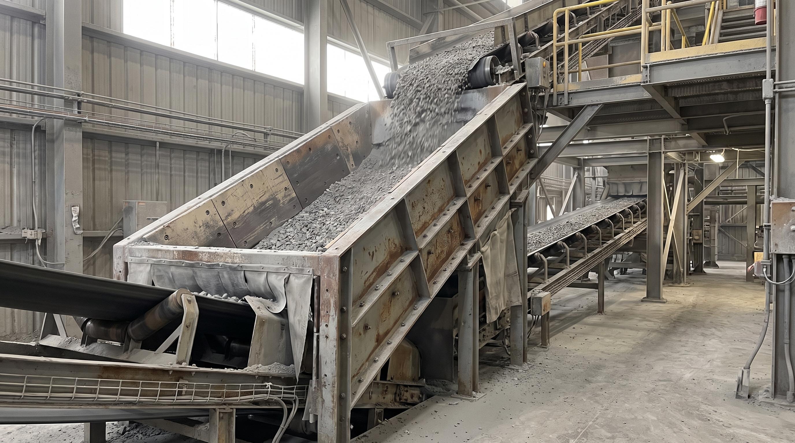
A good diverter chute controls material flow without plugging, spilling, or damaging nearby equipment. The right design depends on lump size, abrasiveness, pressure conditions, and how fast the chute must switch. Flap gate diverters work well for fine to medium powders. Bucket diverters are better for heavy, abrasive ore and rock. Pant-leg chutes are useful when two lines need to stay separate. Good trajectory design, replaceable wear liners, and strong safety practices help reduce wear, dust, and unplanned downtime.
In high-tonnage plants such as mining, cement, grain, steel, and power facilities, diverter chutes control how material moves through conveyor networks. They are placed at key discharge points to split or redirect material to crushers, storage silos, bypass lines, or downstream process circuits.
Diverter chutes may look simple, but poor design often causes plant stoppages. Wrong valley angles can lead to buildup and plugging. Bad trajectory design can damage the receiving belt. Poor sealing can also release dust and create safety and compliance problems under standards set by the Mine Safety and Health Administration (MSHA).
This design guide explores the core mechanical types of diverter chutes, key engineering calculations, wear lining selection criteria, and practical system integration strategies.
Major Types of Diverter Chutes & Application Selection
Choosing the right chute geometry and diverter mechanism depends directly on bulk material density, moisture, abrasiveness, and lump size.
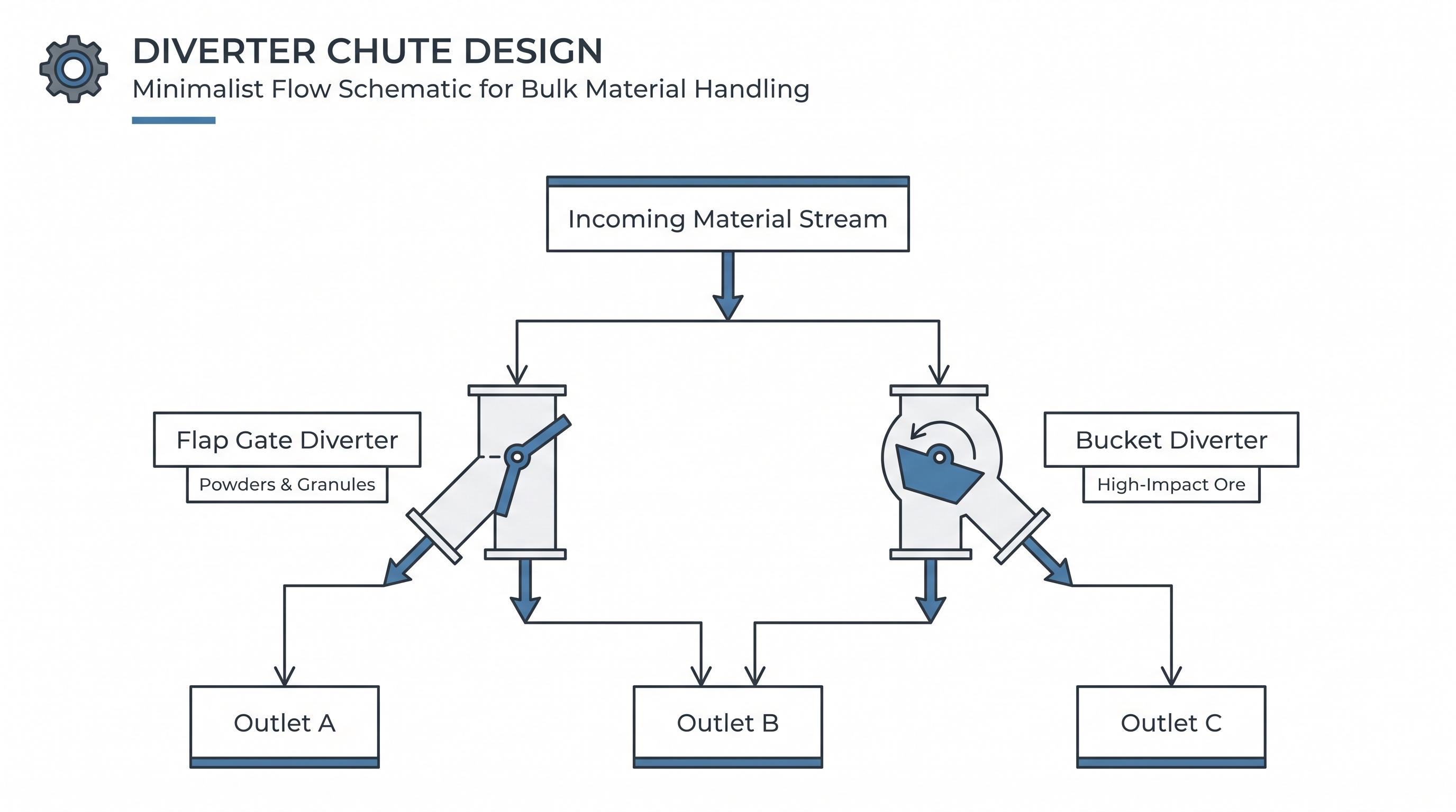
1. Flap Gate (Flop Gate) Diverter Chutes
Mechanism: A internal pivoting blade (flap) mounted on a heavy-duty shaft rotates across the material stream to direct flow into one of two output legs.
Best Used For: Fine to medium granular solids, coal, grains, wood chips, and dry powders with lump sizes generally under 50 mm.
Key Advantage: Compact vertical profile, lower initial weight, and fast actuation cycles using pneumatic cylinders or electric actuators.
Engineering Limitation: Unsuitable for large, high-impact rock that can jam under the internal blade edge or bend the pivot shaft.
2. Bucket (Ladle) Diverter Chutes
Mechanism: A reinforced internal bucket or basket swings through the material trajectory, receiving the falling stream and channeling it to the secondary outlet. When retracted, the stream falls directly into the primary outlet.
Best Used For: Highly abrasive, heavy materials such as iron ore, primary crushed stone, clinker, and copper concentrate with large lump sizes (>100 mm).
Key Advantage: The bucket structure absorbs the direct impact force, protecting the outer casing walls from direct kinetic wear.
Engineering Limitation: Requires a significantly larger vertical drop height (headroom) and heavier support steelwork.
3. Pant-Leg (Slide Gate / Dual-Blade) Chutes
Mechanism: Utilizes two independently controlled slide gates or an integrated Diverter Valve mounted at the bifurcation point of a symmetrical "Y" chute housing.
Best Used For: Process loops requiring full isolated shutoff, variable percentage flow splitting, or clean room environments handling pharmaceuticals and fine chemicals.
Key Advantage: Allows 100% isolation of either leg for downstream maintenance while the primary process line remains operational.
When feeding material from heavy storage vessels into diverter assemblies, integrating a rugged Screw Conveyor or a dust-sealed Airslide Assembly upstream ensures a steady, non-surging discharge rate.
Evaluating trajectory dynamics, headroom limits, or wear liner options for an upcoming conveyor upgrade? Download this comprehensive engineering specification sheet for quick technical baseline parameters.
Core Engineering Standards & Design Criteria
A reliable diverter chute needs more than a strong shell. Engineers must check material speed, impact angles, valley angles, and structural strength. These choices should follow accepted guidance such as CEMA standards.
1. Valley Angle and Flowability
The valley angle is the shallowest line of slope formed by the intersection of two sloping chute side-walls. If the valley angle is less than the material's wall friction angle, material will build up in the corners and cause line blockages.
Minimum rule of thumb: The chute valley angle should be at least 10° to 15° steeper than the static angle of repose for the bulk solid.
Free-flowing dry grains and plastics: 45°–50° wall slope.
Moist coal, limestone, and copper ore: 60°–70° wall slope.
Cohesive clays and sticky minerals: minimum 75° wall slope, combined with polished stainless steel liners or ultra-high-molecular-weight polyethylene (UHMW-PE).
2. Material Trajectory and Velocity Control
Calculating the trajectory path as bulk material discharges from a head pulley or conveyor belt is essential. Material should impact chute walls at an angle of ≤ 15° (grazing impact) to minimize abrasive wear, or strike a designed rock box (dead bed) where material builds up to absorb subsequent impacts.
Centralizing the load as it exits the chute onto a downstream Belt Conveyor System is critical. Off-center loading creates uneven belt tracking, severe spillage, and frame damage on Conveyor Rollers and drive components around the Conveyor Pulleys.
3. Wear Lining Selection Matrix
Chute body steel (typically Grade 250 / A36 carbon steel) must be protected by replaceable internal wear liners engineered for the specific material characteristics:
Liner Material | Key Properties | Recommended Application |
AR400 / AR500 Steel Plates | High hardness (400–500 HBW), good impact resistance. | General mining, limestone, medium-abrasion ores. |
Alumina Ceramic Tiles (92%–95% Al₂O₃) | Extreme sliding abrasion resistance, low coefficient of friction. | Fine abrasive slurries, fly ash, dried clinker. |
Chromium Carbide Overlay (CCO) | Hardfaced weld deposit, extreme gouging wear resistance. | Primary crusher discharge, oversized iron ore lumps. |
UHMW-PE / Polyurethane | Non-stick, low-friction, corrosion-resistant, noise-reducing. | Fine wet powders, sticky clay, wood chips, and grain. |
4. Actuation and Sealing Mechanisms
Diverter blades require reliable drive mechanisms to transition position cleanly under full material load:
Pneumatic Actuators: Ideal for quick switching (under 2 seconds) on light-to-medium material streams.
Electric Electro-Mechanical Actuators: Preferred for heavy-duty gates requiring high thrust forces, precise positioning, or integration into automated PLC system architectures.
Shaft Seals & Dust Containment: Shaft entries must feature adjustable packing glands or air-purged seals to contain fine dust particles in compliance with environmental regulations maintained by the US Environmental Protection Agency (EPA).
Need assistance sizing a diverter chute, calculating trajectory profiles, or selecting wear liners for your bulk material handling line? Our application engineering team can help.
From the Field: A copper mining plant had repeated chute failures at a transfer tower handling 3,200 metric tons per hour of wet crushed ore with a 150 mm top size. The original pant-leg diverter chute used 12 mm AR400 liners and a 45° impact slope. Material from the upper feed belt hit the internal flap almost head-on. In just 6 weeks, the ore wore through the liner and cut into the outer steel shell. The secondary leg also discharged off-center, which caused belt mistracking on the receiving conveyor. The fix was a curved rock-box hood that allowed a material pocket to absorb the first impact. The internal flap was replaced with a heavy-duty bucket diverter lined with 25 mm Chromium Carbide Overlay (CCO) plates. The discharge path was also adjusted to center the load on the lower belt.
Final Key Takeaways
Successful diverter chute design requires careful evaluation of material dynamics, mechanical geometry, and wear protection. By accurately projecting material trajectories according to CEMA standards, selecting valley angles steep enough to eliminate plugging risks, and specifying wear liners suited to bulk solid abrasiveness, engineering teams can build reliable transfer circuits. Investing in proper actuation, dust-tight shaft sealing, and centered discharge profiles protects receiving belts, extends liner life, and ensures long-term operational efficiency.
Frequently Asked Questions(FAQs)
Centered discharge keeps the downstream belt evenly loaded, which helps prevent mistracking, spillage, uneven roller loading, and premature damage to pulleys and structure. Even a well-lined chute can create downstream problems if material exits off-center.
Wear is reduced by controlling material trajectory, minimizing direct impact angles, and using replaceable liners suited to the conveyed material. Designs that create a dead bed or rock box, centralize discharge onto the receiving belt, and use materials such as AR400/AR500, ceramic liners, or Chromium Carbide Overlay (CCO) can extend service life significantly.
As a practical rule of thumb, the chute valley angle should be at least 10° to 15° steeper than the material’s static angle of repose. In real applications, free-flowing materials may work with 45° to 50° wall slopes, while wetter or more cohesive materials often need 60° to 75° or more to prevent buildup and plugging.
A flap gate diverter is generally better for fine to medium granular materials, dry powders, and lighter-duty applications where fast actuation and a compact layout matter. A bucket diverter is better for heavy, abrasive, or large-lump materials because it absorbs more impact and protects the chute casing from direct wear.