
How to Size and Specify a Flow Control Gate for Stable Hopper and Silo Discharge

Vijay Baid
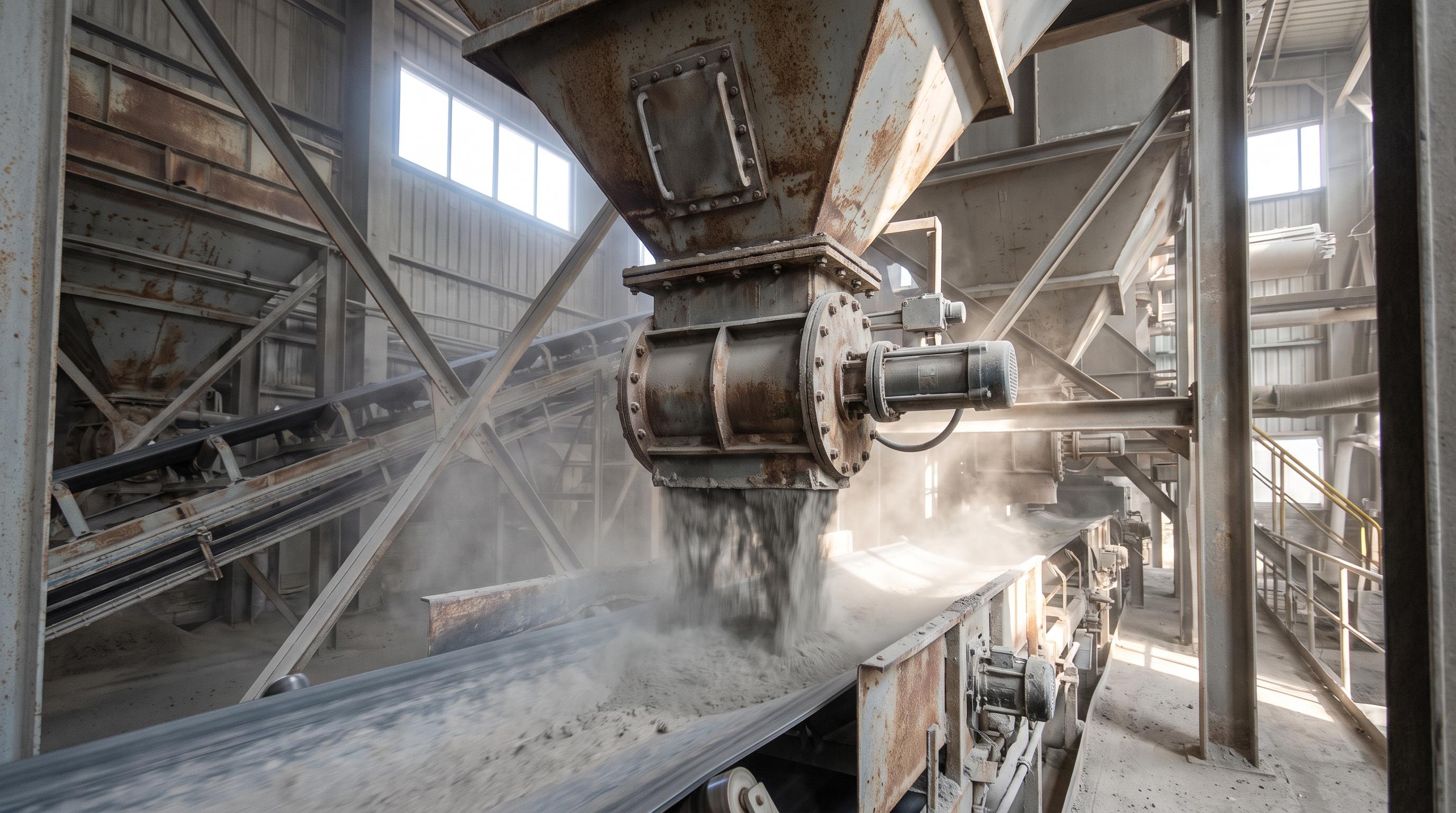
Sizing a flow control gate starts with the material profile: bulk density, particle size, flowability, abrasiveness, and moisture all affect the opening, seals, and actuation you need. The gate should be sized to avoid choking and specified as part of the full hopper-to-discharge system so flow stays stable, dust-tight, and controllable under load. Poor sizing or unsupported installation leads to bridging, leakage, blade binding, and actuator overload.
In bulk material handling, treating a flow control gate as an afterthought creates avoidable problems. Gates that are too small can choke production and cause bridging, where material arches over the opening. Gates that are too large, or poorly specified, can flood the line, cause flushouts, and wear out downstream equipment faster.
Whether you handle abrasive iron ore, sticky clinker fines, or fluidizing cement powder, stable discharge starts at the hopper or silo outlet. That point needs careful mechanical design if you want steady flow and fewer operating issues.
1. Establish the Material Profile
Before you review a catalog or open a CAD file, define the exact physical properties of the bulk solid. The gate material, seals, and drive type should match the product. They should not force the product to behave in a way it naturally will not.
From Site Assessments: In cement plants, we often find that the gate was selected from a standard size chart before anyone checked the actual material profile at the outlet. On site, that usually shows up as intermittent choking during wet-season operation, when higher moisture changes how the material packs and discharges.
Bulk Density & Particle Size: Calculate the maximum bulk density (typically in kg/m3 or lb/ft3)and the largest expected particle size (d90).
Flowability (Angle of Repose): Highly cohesive materials require different gate geometries than free-flowing powders.
Abrasiveness & Corrosiveness: Abrasive clinker or raw ores require hardened liners, while corrosive chemical compounds demand stainless steel constructions.
2. Sizing the Gate Opening (The No-Choke Calculation)
A flow control gate should not set the minimum opening needed to stop bridging. That job belongs to the hopper design. The gate should match that opening, or be slightly larger, so it does not become the choke point.
To prevent physical interlocking or mechanical arching, use these two fundamental rules of thumb for minimum sizing:
Coarse / Granular Materials
For large, sized bulk solids, the minimum gate dimension must scale with particle size to prevent jamming:
Minimum Gate Opening ≥ 3 × Maximum Particle Size (d₉₀)
Fine / Cohesive Powders
To prevent bridging or ratholing, the opening must be larger than the critical arching dimension calculated via bulk solids mechanics (typically based on the material's unconfined yield strength).
Field Rule of Thumb: For fine powders prone to packing, a minimum opening of 300 mm to 450 mm (12" to 18") is generally required to guarantee self-executing gravity flow, regardless of volumetric throughput requirements.
If you are preparing a specification or comparing vendors, document the gate opening, blade design, seal arrangement, actuator duty, and material compatibility together. A practical spec sheet helps your team review the full hopper-to-discharge requirement before finalizing a gate for abrasive, dusty, or high-head applications.
3. Understand the Anatomy of a Slide Gate
To specify the correct unit, you need to speak the language of gate manufacturing. High-performance gates use modular assemblies to allow inline component swaps during planned maintenance shutdowns.
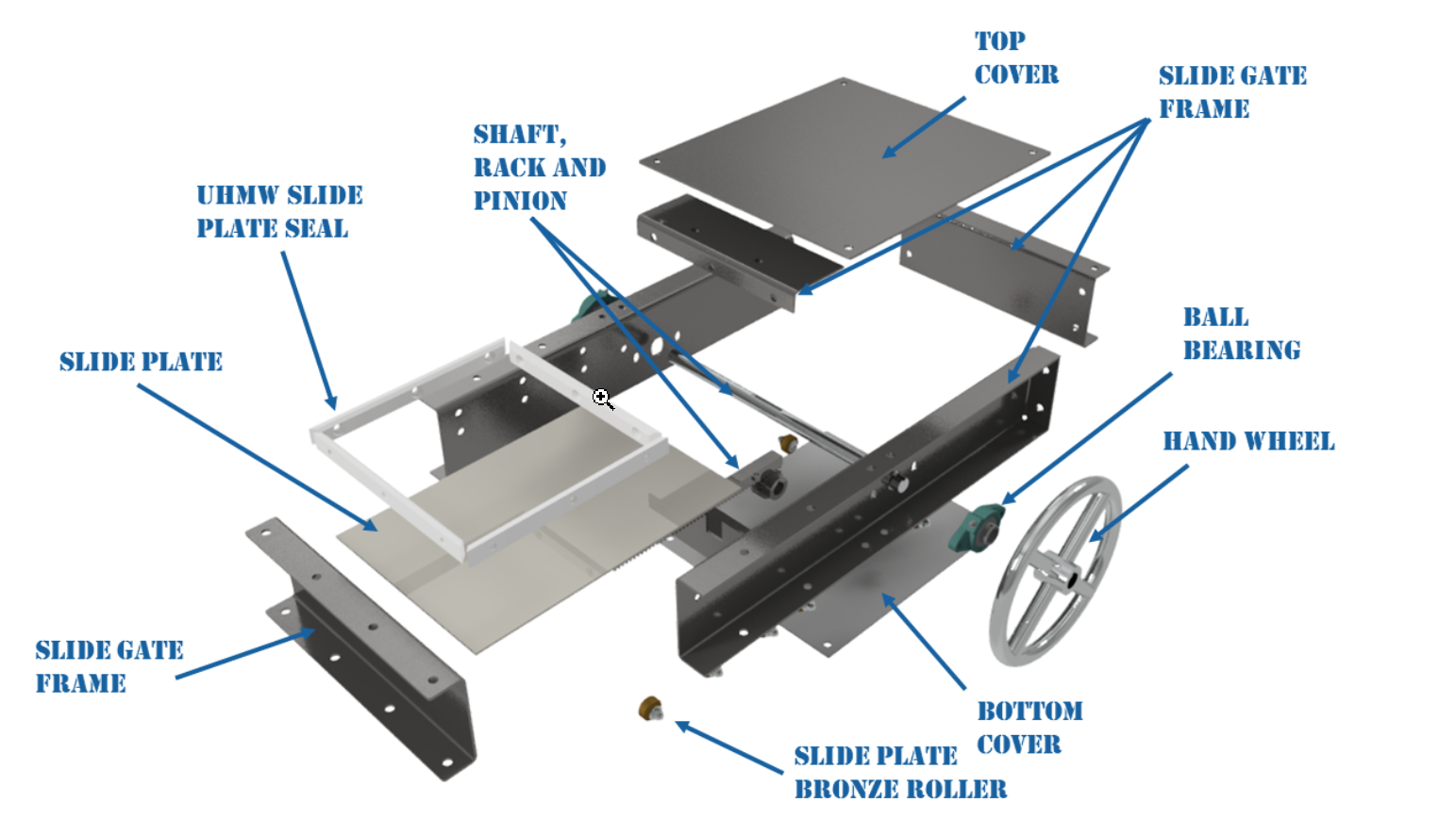
When handling fine powders, you must specify robust materials like a UHMW Slide Plate Seal to wrap completely around the blade. This prevents atmospheric dust leaks and keeps the blade traveling along a smooth plane without binding against the frame. Ensuring dust-tight containment is also critical to stay compliant with international workplace ambient safety mandates like the U.S. OSHA Combustible Dust Standards.
4. Selecting the Right Gate Type for Your Application
Different flow control challenges demand different mechanical designs. Specifying the wrong structural style will cause material leakage or blade jamming.
Gate Type | Best For | Core Operating Advantage | Main Operational Limit |
Heavy-Duty Slide Gate | Coarse materials, coal, and aggregates | Total material isolation, robust blade structural integrity | Higher friction; can pinch fine powders if unsealed |
Vee-Orifice / Needle Gate | Fine metering of free-flowing dry powders | Precise volumetric flow adjustment via variable V-port profile | Not suitable for large particle chunks |
Clamshell / Sector Gate | High-volume batch weighing and loading | Ultra-fast emergency cutoff capabilities | High vertical space requirement under the hopper |
5. Match the Actuation to the Process Control
How you drive the gate blade depends on whether you need a simple maintenance isolation block or dynamic closed-loop process flow adjustment.
Pneumatic Actuators | Best for high-speed open/close cycles (Batching, weighing, instant cutoff) |
Electric Actuators | Ideal for infinite modulating control (Closed-loop feeding, precise positioning |
Manual Handwheels | Reserved for maintenance isolation gates (Infrequent operation only) |
Erratic silo discharge or gate binding affecting production? Get a customized hopper-to-gate assessment from our application engineers to optimize material flow and prevent costly design mistakes.
From the Field: A major cement plant had repeated electric actuator failures on a silo discharge gate handling raw meal. The actuator kept tripping on thermal overload. When we inspected the system, we found no top cover protection and no internal deflector cones. As a result, the weight of a 40-meter material column was pressing directly on the horizontal slide plate.
The resulting normal force created a friction lock that exceeded the actuator’s rated force capacity by 200%. Adding a structural static pressure relief saddle right above the gate inlet isolated the blade from the material column weight, allowing the system to modulate smoothly with 60% less torque. To understand how material flow profiles affect structural loading, refer to the U.S. Bureau of Reclamation Engineering Standards for Conveyors and Silos.
Final Takeaway
Sizing a flow control gate is more than just matching a flange to an existing hopper outlet. It requires looking at the bulk solid profile, calculating the arching limits to avoid choking, and selecting a mechanical seal that keeps the product inside the line. By configuring the gate as part of an integrated, engineered network alongside high-efficiency Transfer Chutes and rugged Belt Conveyor Systems, you prevent spillage, protect downstream feeders, and maintain a highly stable, predictable discharge loop.
Frequently Asked Questions (FAQ)
An isolation gate (often called a maintenance gate or knife gate) is designed strictly for binary open/close operation to shut off material flow during downstream maintenance. A flow control gate features heavy-duty variable positioning (via electric or modulating pneumatic actuators) and hardened blade geometries designed to meter and regulate precise, continuous volumetric flow rates under a live material column.
Standard metal-to-metal seats will leak fine powders. You must specify a gate featuring adjustable perimeter packing glands combined with high-density UHMW-PE (Ultra-High-Molecular-Weight Polyethylene) or braided PTFE compression seals. Additionally, incorporating a displacement pocket at the back end of the gate frame gives the blade a place to push material without packing it into a solid wedge.
While gates can operate horizontally, installing a slide gate at a 45o to 60o angle (matching the hopper wall slope) is preferred for sticky or cohesive materials. This keeps the material moving along the natural mass-flow angle and minimizes dead zones inside the gate frame where material can pack, harden, and stall the blade.
Blade binding is almost always caused by static material head-load. If a gate is placed directly beneath a high-capacity silo without a structural deflection cone, static pressure saddle, or offset drop chute, the immense weight of the material column forces the blade to deflect downward into its tracking frame, creating severe friction-lock.
As moisture increases, dry powders become sticky cakes, drastically increasing their unconfined yield strength. For materials with fluctuating moisture levels (such as ambient stored ores or coal), you must specify 304 or 316 stainless steel liners to prevent rust-pitting (which destroys gate seals) and upgrade the actuator to a high-thrust pneumatic cylinder to overcome stick-slip friction