
Impact Idlers for Cement Plants: Specifications, Selection & Installation Guide

Vijay Baid

Impact idlers protect conveyor belts at cement plant transfer points by replacing rigid steel rollers with shock-absorbing rubber or polyurethane rings. When heavy limestone or hot clinker drops from a chute, these rings cushion the blow reducing impact force by over 90% to prevent severe belt cuts, tears, and premature bearing failure. For cement plants, specify heavy-duty CEMA D or E idlers with triple-labyrinth dust seals, and space them closely together every 300 mm to 450 mm under loading chutes to stop belt sag and keep abrasive dust contained.
Cement plants are hard on conveyors. Limestone, clinker, and other bulk material hit belts, chutes, and rollers all day. Transfer points take the most abuse.
A 15 kg limestone lump falling 3 meters hits the belt with a lot of force. If it lands on a rigid steel roller, the belt takes the damage. That can lead to cuts, torn plies, bent shafts, and failed bearings.
To avoid costly breakdowns, engineers need to look past basic belt size and speed. The impact zone needs the right idlers, spacing, and support. That is what keeps a cement conveyor running reliably.
This guide breaks down the technical specifications, selection calculations, and installation mistakes to help you protect your plant's conveyors from impact damage.
The Physics of Conveyor Impact Zones
To protect a high-speed conveyor belt, you must understand the dynamic forces at play when bulk materials drop onto it.
When raw limestone, shale, or gypsum falls from an upper chute onto a conveyor belt, it carries kinetic energy (Ek):
Ek = m . g . h
Where:
m = mass of the largest material lump (kg)
g= acceleration due to gravity (9.81 m/s2)
h = drop height from the chute to the belt (m)
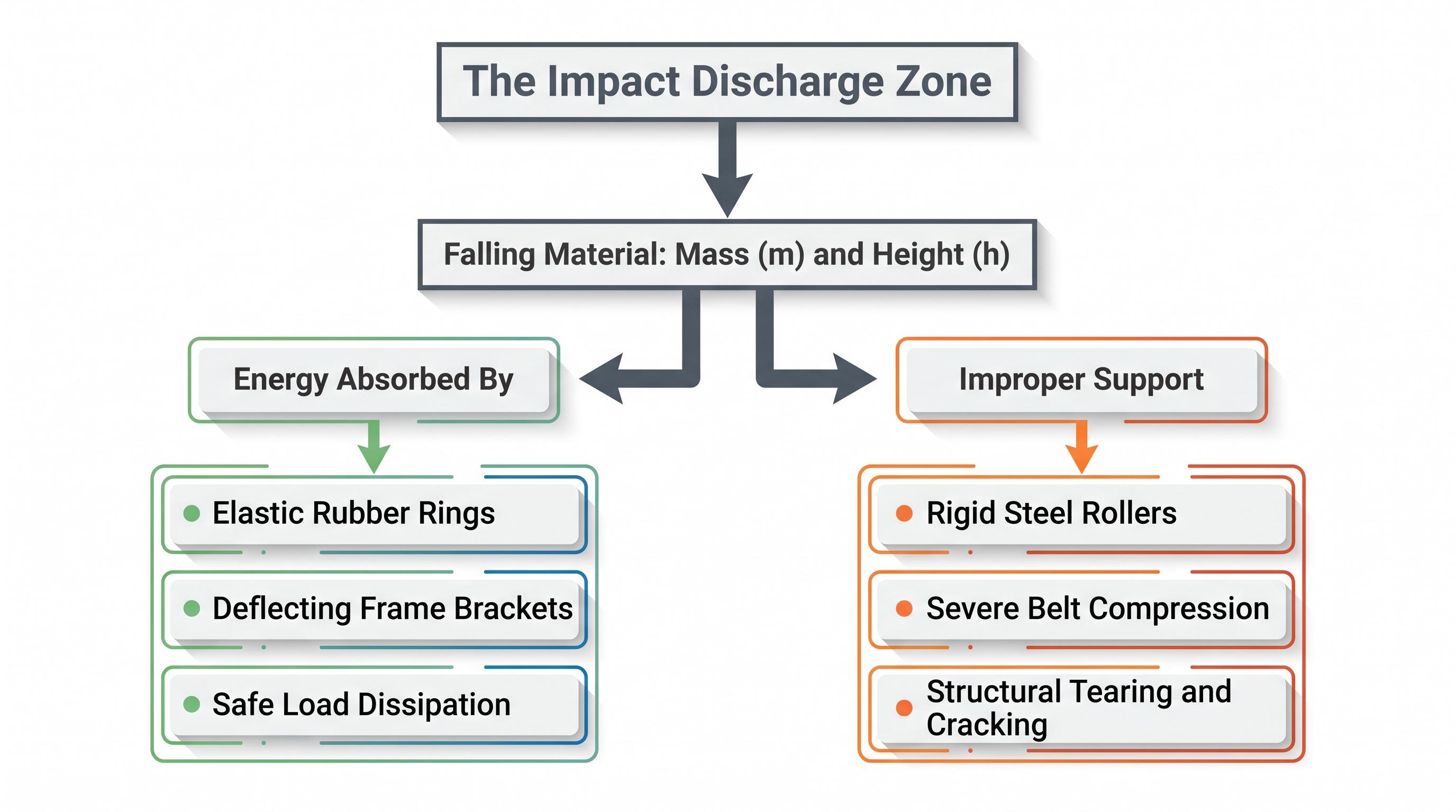
When this falling material hits the belt, that kinetic energy must be absorbed. If standard steel-walled Carrying Idlers are used directly under the chute, the belt carcass is compressed between the falling lump and the rigid steel roller. This crushing action causes micro-punctures, ply separation, and immediate belt tearing.
Impact idlers solve this problem by replacing the rigid steel tube with a series of high-durability rubber or polyurethane rings mounted on a heavy-walled steel core.
When material hits the belt, these rings compress, absorbing the impact energy and preventing belt damage.
Technical Comparison: Impact Idlers vs. Impact Cradles
For heavy material drop zones, plant engineers must choose between impact idlers and impact cradles (also known as impact beds). The table below compares these two options to help you choose the right design for your transfer points:
Operating Parameter | Rubber-Ring Impact Idlers | Heavy-Duty Impact Cradles |
Material Lump Size | Small to Medium (< 150 mm) | Large to Extra-Large (> 150 mm) |
Drop Height | Low to Moderate (< 1.5 m) | High ( 1.5 m) |
Primary Advantage | Low rotational friction, lower power draw | Flat sealing surface, prevents belt sag |
Maintenance Profile | Rollers can be replaced individually | Slide-out bars require periodic replacement |
Sealing System Fit | Poor fit for dust skirts; creates belt sag | Excellent fit; provides a flat sealing surface |
Best Positioned In | Secondary sizing, clinker, gypsum loops | Primary crushing feed, main quarry chutes |
Are frequent roller failures, severe belt mistracking, or excessive spillage at your transfer points increasing your plant's manual maintenance costs? Stop dealing with conveyor downtime.
Selection Factors: Engineering Your Layout
Before specifying an impact idler from a manufacturer's catalog, three key engineering parameters must be evaluated:
1. Determining the CEMA Rating
CEMA groups idlers by duty level. The rating depends on load, belt width, roll diameter, speed, and expected bearing life. Use the standard as a guide when you compare options. For the full standard, see the official CEMA (Conveyor Equipment Manufacturers Association) guidelines.
CEMA Class is directly propto f(Load, Belt Width, Roller Speed, Bearing L10 Life)
CEMA B/C: Designed for light to medium duties like agricultural processing, light sand, or gravel.
CEMA D/E: Designed for heavy-duty coal, cement clinker, and steel-plant raw material processing.
CEMA F: Reserved for extra-high capacity, high-speed, overland mine runs.
For cement plants handling raw limestone, always specify CEMA D or E impact idlers. Using under-rated rollers will result in rapid shaft deflection, misaligning the bearings and causing early roller failure.
2. Bearing and Seal Configuration
Cement, sand, and clinker dust wear out rollers fast. If dust gets past the seals, it reaches the bearings. Once that happens, bearing life drops quickly.
Triple-Labyrinth Seals: This design forces grease through a winding path, keeping fine dust from reaching the ball bearings.
Sealed-for-Life Bearings: Quality industrial rollers use sealed-for-life ball bearings. These systems eliminate the need for manual lubrication, lowering maintenance costs and ensuring consistent performance. High-performance bearing standards often reference ISO (International Organization for Standardization) guidelines to verify dimensional tolerances and material fatigue life under load.
3. Impact Ring Material and Roll Diameter
The ring material and roll diameter directly affect how much energy the idler can absorb:
SBR Rubber Rings: Standard Styrene-Butadiene Rubber (SBR) provides excellent elasticity and shock absorption for standard limestone and clinker applications.
Polyurethane Rings: For extreme environments with high material temperatures or oily additives, polyurethane offers superior wear resistance and a longer service life.
Roller Diameter: Use larger roll diameters (such as 152 mm or 178 mm instead of 127 mm) for high-speed belts. Larger rollers turn at lower RPMs to match the same belt speed, keeping bearing temperatures lower and extending overall roller life.
Common Installation and Design Mistakes
Even high-quality impact idlers will fail early if installed incorrectly. Avoid these common mistakes:
Inadequate Idler Spacing: Spacing impact idlers too far apart under a loading chute is a common error. Standard carrying idlers are spaced at 1.0 m to 1.5 m intervals, but impact idlers must be spaced closely together every 300 mm to 450 mm to prevent the belt from sagging between rollers.
Incorrect Frame Alignment: The impact zone must match the trough angle of the rest of the conveyor. If your carrying run uses a 35o trough, your impact idlers must also use a 35o frame. Using mismatched angles creates high-stress points that can tear the belt.
Ignoring Skirt Rubber Clearances: When impact rollers are spaced too far apart, the belt sags between the rollers under the weight of the material. This sag creates gaps between the belt and the containment skirts, allowing fine dust to escape and spill onto the plant floor.
Need the key parameters in one place? Download the spec sheet for a quick reference on impact idler selection, spacing, sealing, and cement-duty suitability before you finalize your transfer-point layout.
From the Field: During an audit at a cement plant, we found the maintenance crew replacing several torn conveyor belts every year along their primary limestone reclaim conveyor. The plant had recently updated their quarry chutes to handle larger limestone chunks but left the original steel carrying idlers directly under the drop point.
The constant impact of the falling limestone had shattered the bearings inside the middle steel rollers, locking them in place. The moving belt was dragged across these frozen steel faces, wearing them down into razor-sharp edges that sliced long grooves into the lower belt cover, threatening to split the expensive belt lengthwise.
We resolved the issue by replacing the first six steel frames under the chute with heavy-duty CEMA D impact idlers fitted with triple-labyrinth grease seals and larger 152 mm diameter rolls. We also spaced the new rollers closely together every 350 mm to eliminate belt sag. This change completely stopped bearing failures, and the conveyor belt has now run smoothly for over two years without a single unscheduled shutdown.
Final Takeaway
A reliable conveyor system starts with the right idler at each point in the line. Use heavy-duty carrying idlers where you need load support. Use rubber impact idlers under feed chutes. Use self-aligning return idlers where tracking is a concern.
Your idler layout should also match the equipment that moves material after the belt conveyor. That can include Belt Conveyors, Screw Conveyors, and Diverter Valves. When these systems work together, you reduce unplanned shutdowns and keep material moving safely through the plant.
Frequently Asked Questions (FAQ)
Under feed chutes, impact idlers must be spaced much closer together than standard carrying idlers. The industry standard is 300 mm 450 mm (12 to 18 inches) between centerlines. This close spacing prevents the belt from sagging under the weight of falling material.
Use an impact cradle for high-drop transfer points (drops over 1.5 meters) or when handling large, heavy material chunks (over 150 mm in size). Cradles feature long, low-friction slider bars that support the entire length of the impact zone, providing a flat surface that prevents material spillage and belt damage.
When falling material hits the belt, the rubber rings on the impact idler deflect under the load. This compression absorbs the kinetic energy of the impact, preventing the belt carcass from being crushed against a rigid steel surface.
Standard rubber impact rings degrade and lose their elasticity when exposed to temperatures above 80o C (176o F). For hot clinker lines, always specify high-temperature elastomer or polyurethane rings designed to handle high heat without melting.
No. Standard steel rollers cannot absorb impact forces. The constant pounding of falling material will deform the steel shells, bend the internal shafts, and quickly destroy the bearings, leading to roller failure and belt damage.