
Rotary Airlock Valve Troubleshooting: 10 Common Problems & Engineering Solutions

Vijay Baid
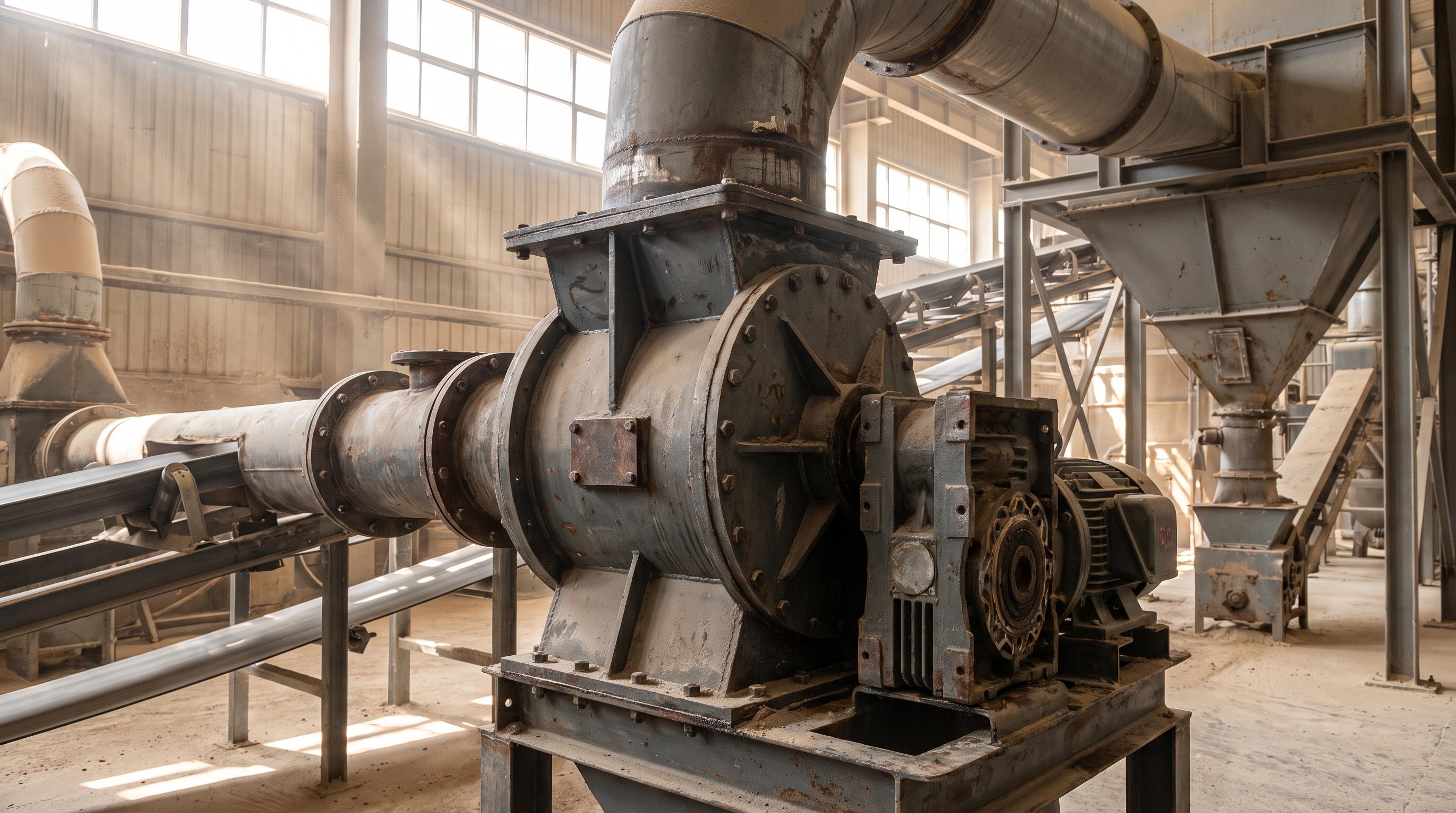
Troubleshooting a failing rotary airlock valve requires tracing mechanical symptoms back to root system imbalances. The most common problems such as material bridging in the supply hopper, severe motor overloading, and fugitive dust leaking from the shaft usually stem from excessive internal blowback air, incorrect rotor clearances (exceeding 0.15 mm), or thermal expansion binding. By properly venting displacement air, matching rotor geometries to material abrasiveness, and adjusting shaft packing glands, plant engineers can eliminate continuous bottlenecks and restore full throughput to their pneumatic conveying lines.
In any pneumatic conveying system, the rotary airlock valve is the critical boundary between differing pressure zones. Because it handles the dual responsibility of metering bulk solids while sealing against pressurized air, it is naturally subjected to severe mechanical stress, abrasion, and temperature fluctuations.
When an airlock begins to fail, the symptoms rarely stay isolated to the valve itself. A worn rotor tip allows high-pressure convey air to blow back into the upstream hopper, fluidizing the material and causing complete feed starvation. A damaged shaft seal leaks hazardous dust into the plant atmosphere, triggering compliance violations with OSHA (Occupational Safety and Health Administration) air quality standards.
Rather than continually replacing blown motors or worn rotors, maintenance teams must identify why the valve is failing. This guide breaks down the 10 most common rotary airlock problems, their engineering root causes, and how to fix them permanently.
The Top 10 Rotary Airlock Problems & Solutions
1. Excessive Air Blowback (Inlet Bridging)
The Problem: Material stops flowing from the upstream hopper into the airlock. Looking through the sight glass, the powder appears fluidized, bubbling, or suspended in mid-air.
The Root Cause: High-pressure conveying air is escaping past the rotor tips and shooting straight up the inlet throat.
The Fix: Check internal rotor clearances with a feeler gauge. If the gap exceeds 0.20 mm, replace the rotor or adjust the tips. If the clearances are still tight, the issue is usually displacement leakage. Install a vent box (blowback shoe) directly above the valve inlet to vent returning air to a dust collector before it reaches the material.
2. Sudden Rotor Jamming
The Problem: The valve locks up completely, tripping the motor breaker or snapping the shear pin.
The Root Cause: Large tramp metal, oversized lumps, or stringy materials are getting pinched between the rotating vane and the V-shaped inlet housing shear point.
The Fix: Install a magnetic grate above the valve to catch tramp metal. For stringy or oversized product (like wood chips), swap to a flexible tip rotor (polyurethane) or install a deflector baffle in the inlet throat to prevent pinching.
3. Rapid Rotor Tip Wear
The Problem: A new valve loses its pressure seal within a few months, and blowback returns.
The Root Cause: Handling highly abrasive materials (e.g., fly ash, silica sand, clinker) with standard mild steel or 304 SS open-end rotors.
The Fix: Upgrade to a closed-end (shrouded) heavy-duty Rotary Airlock Valve coated with hardened tungsten carbide or Ni-Hard alloys. Ensure a Transfer Chute drop-out box is installed on the discharge side so high-velocity abrasive air doesn't blast directly into the rotor pockets.
4. Shaft Packing Gland Leaks (Fugitive Dust)
The Problem: Fine powder is constantly blowing out of the sides of the valve where the shaft exits the housing.
The Root Cause: The internal braided packing rings have worn down or dried out, breaking the mechanical seal.
The Fix: Tighten the packing gland followers evenly. If the leak persists, replace the PTFE/graphite packing. For aggressive micro-powders, upgrade to air-purged shaft seals, which inject plant air at about 3 psi above line pressure to actively push dust away from the bearings.
If you're evaluating clearances, rotor options, seal arrangements, or material compatibility, this spec sheet gives you a quick technical reference before you select or replace a rotary airlock valve.
5. Metal-on-Metal Squeaking & Grinding
The Problem: The valve emits a loud, rhythmic scraping sound while rotating.
The Root Cause: The rotor is physically rubbing against the internal housing or endplates. This is usually caused by thermal expansion when handling hot materials above 100°C without clearance offsets, or by a failing outboard bearing allowing the shaft to sag.
The Fix: Stop the valve immediately to prevent severe housing gouging. Check bearing runout. If handling hot materials, you must order rotors with pre-machined "high-temp clearances" to account for the metal expanding.
Selecting the right internal clearances, rotor geometry, and seal materials is highly dependent on your specific material's bulk density and temperature profile. Using a generic replacement valve often leads to repeating the exact same mechanical failures.
6. Motor Overloading & Gearbox Failure
The Problem: The drive motor pulls excessive amperage, runs extremely hot, and the gearbox eventually fails.
The Root Cause: The valve is running too fast (high RPM) and failing to fill, or sticky material is packing into the clearance gaps and acting like a brake pad against the housing walls.
The Fix: Verify the operating speed, ideally 12-20 rpm. If the material is sticky or cohesive, switch to a reduced-volume chamfered rotor or apply a non-stick Teflon/fluoropolymer coating to the internal housing.
7. Capacity Drop (Throughput Starvation)
The Problem: The system is falling short of its tons-per-hour (TPH) target, even though the rotary valve is running at full speed.
The Root Cause: Over-speeding. If a valve spins faster than 30 rpm, centrifugal force prevents gravity from pulling the material into the pocket before it rotates past the inlet.
The Fix: According to CEMA capacity standards, larger pockets rotating slower always yield higher volumetric efficiency than small pockets spinning fast. Decrease the VFD speed to allow pockets to fill to about 80% capacity.
8. Material Smearing inside Pockets
The Problem: Sticky materials (e.g., milk powder, hydrated lime, wet clays) build up in the corners of the U-shaped rotor pockets, reducing the functional volume of the valve by half.
The Root Cause: Poor pocket release characteristics.
The Fix: Convert to a blow-through rotary airlock. Instead of relying on gravity to drop the material out, the pneumatic convey line is piped directly through the bottom of the rotor housing, aggressively blasting the pockets clean on every revolution.
9. Housing Endplate Gouging
The Problem: When rebuilding the valve, deep circular grooves are found cut into the side endplates.
The Root Cause: Abrasive material is falling between the side of the open-end rotor vanes and the stationary endplates, grinding away the metal.
The Fix: This is a classic misapplication. Abrasive lines must use closed-end (shrouded) rotors, which feature solid metal discs welded to the sides of the vanes to protect the housing endplates from direct material contact.
10. Failing Combustible Dust Inspections
The Problem: Safety inspectors flag the airlock for failing to act as a certified explosion isolation barrier.
The Root Cause: The valve lacks the heavy-duty housing structure, sufficient vane count, or tight clearances required to prevent a deflagration flame front from passing through.
The Fix: Replace the standard duty valve with an NFPA 69 / ATEX certified explosion isolation airlock. These require heavy ductile iron/steel castings, at least 8-vanes (to maintain 2 vanes in contact with the housing at all times), and maximum clearances of 0.20 mm.
Facing blowback, rotor wear, seal leakage, or throughput loss? Our team can diagnose the cause and recommend the right airlock design, clearances, and dust-control measures.
From the Field: A coal-fired power plant's fly ash handling system experienced repeated failure on a rotary airlock feeding a positive-pressure line at 0.8 bar. Every time the boiler load increased, the fly ash temperature rose from 90°C to 180°C. Shortly after, the airlock would begin squeaking violently before tripping the motor overload.
Plant maintenance assumed the ash was jamming the rotor and repeatedly replaced the drive motors. An engineering teardown revealed heavy galling on the rotor tips. Standard ambient clearances of 0.12 mm had been used. As the hot fly ash heated the solid steel rotor shaft, it expanded radially faster than the cast iron housing, which was exposed to ambient cooling. The 0.12 mm gap disappeared, causing metal-on-metal lockup.
First, we machined a new rotor with a high-temperature offset clearance of 0.25 mm at room temperature, mathematically calculated to shrink to exactly 0.12 mm at 180°C. Second, we swapped the standard bearings for C3 high-clearance, high-temperature bearings.
The metal-on-metal squeaking stopped instantly, motor amperage stabilized, and the valve has run uninterrupted for two years through extreme temperature swings.
Final Takeaway
Troubleshooting a rotary airlock valve is an exercise in balancing mechanical tolerances against system pressures. When blowback occurs, it is physics telling you that high-pressure air has found the path of least resistance. When valves jam or squeak, it is usually a mismatch between rotor geometry, material properties, and thermal expansion. By correctly sizing the valve, installing proper vent boxes, upgrading seal materials, and utilizing standard preventive maintenance, you can eliminate these bottlenecks and protect the efficiency of your entire pneumatic conveying line.
Frequently Asked Questions (FAQ)
Not by default. If the system needs explosion isolation, the valve must be specifically engineered and certified for that duty, with the vane count, clearances, and housing strength required by the applicable standard. A standard-duty valve should not be treated as a certified isolation barrier unless it is explicitly rated for that service.
Closed-end rotors are the better choice for abrasive and high-wear services because they shield the housing endplates from direct material contact. If you're handling materials such as fly ash, clinker, or silica-rich product, a shrouded rotor usually delivers longer sealing life and lower rebuild frequency.
Bridging at the inlet is usually caused by blowback air moving up through the hopper and fluidizing the material before it can fall into the rotor pockets. The first checks should be rotor-tip clearance, wear condition, and whether a vent box or blowback shoe is installed to relieve returning air.
In most standard-duty applications, internal clearances are typically kept tight enough to control blowback while still preventing contact under load. As a practical troubleshooting benchmark, once the gap grows beyond about 0.20 mm, sealing performance usually drops and the valve should be inspected for tip wear, adjustment, or replacement.