
Pneumatic Conveying
Rotary Airlock Valve: Working Principle, Types & Selection Guide for Pneumatic Conveying

Vijay Baid
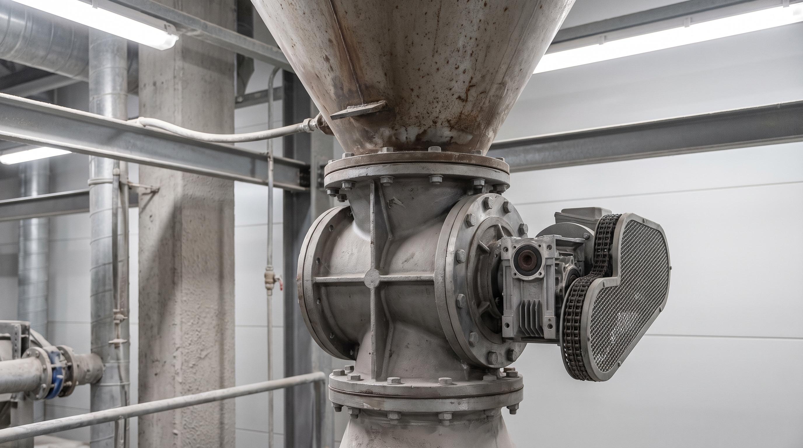
A rotary airlock valve does two jobs in a pneumatic conveying system. It feeds powder or granules at a steady rate, and it helps maintain the pressure difference between the hopper and the conveying line. Good sizing depends on pocket volume, rotor clearance, heat expansion, and blowback air. If the rotor style is wrong or blowback is not vented, the line can bridge, wear faster, and lose throughput.
In bulk solids handling, few parts work harder than the rotary airlock valve. It runs under constant pressure difference and handles abrasive, sticky, or fragile materials. Whether it feeds fly ash into a positive-pressure line or discharges clinker dust from a vacuum cyclone, it controls how material moves into and out of the system.
When it is sized and selected well, a rotary airlock gives steady flow and keeps high-pressure air from pushing back into the silo. When it is not, it becomes a bottleneck. Blowback air can fluidize material at the inlet, cause bridging, wear the housing, and reduce conveying capacity.
This guide explains how rotary airlocks work. It covers rotor selection, blowback calculations, maintenance checks, and practical sizing decisions.
Working Principle: Mechanical Pocket Displacement
A rotary airlock works by moving fixed pockets of material. Material drops into a pocket at the top, turns inside the housing, and then falls into the air stream below.
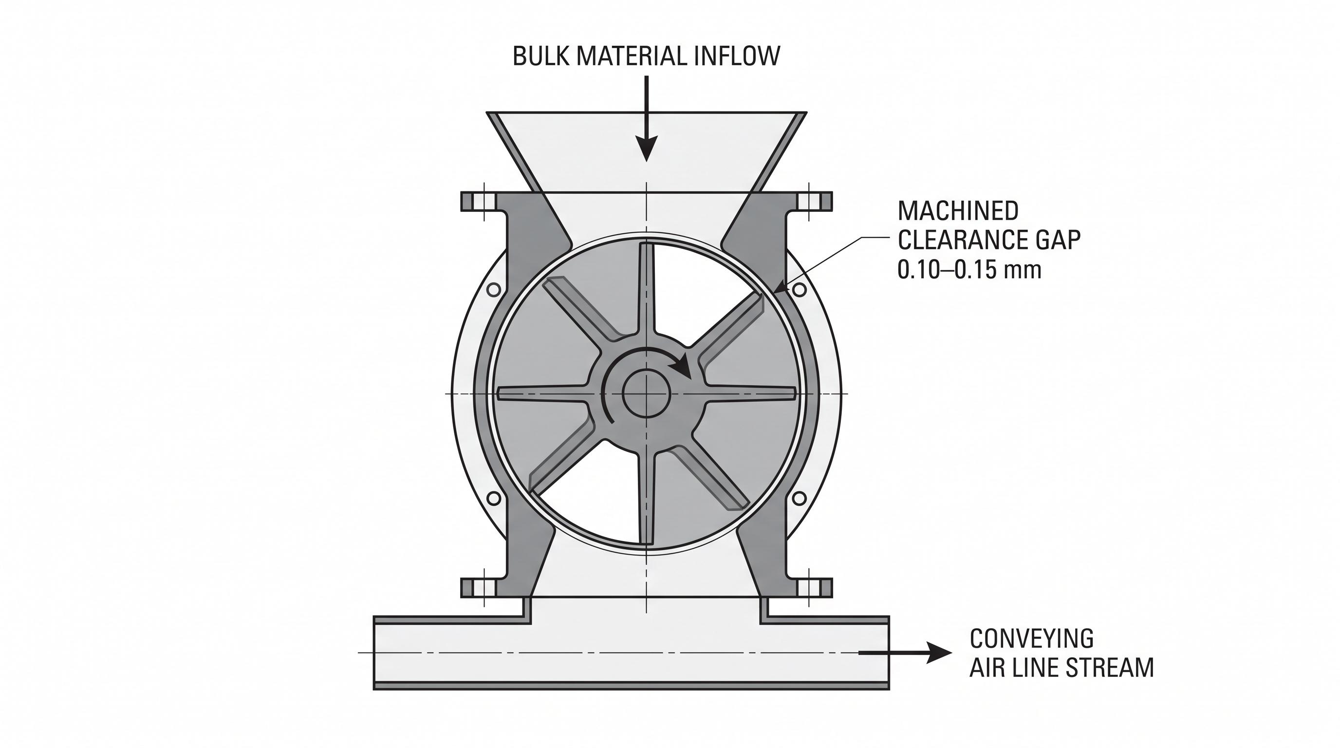
The Dual Role: Metering vs. Sealing
Metering: A motor and gearbox turn the rotor at a low speed, usually 10–25 RPM. Each pocket carries a set amount of material on every turn.
Sealing: The gap between the vane tips and the housing stays very small, usually 0.10–0.15 mm. This helps limit air leakage from the high-pressure side to the low-pressure side.
Rotor Geometry & Selection Criteria
The right rotor design has a big effect on service life. This matters most when the material is abrasive, sticky, or hot.
Rotor Style | Vane Geometry | Ideal Material Applications | Key Advantage |
|---|---|---|---|
Open-End Rotor | Vanes welded directly to central shaft | Free-flowing, non-abrasive powders (flour, starch, plastic pellets) | Maximum pocket volume; lower initial cost and light overall weight. |
Closed-End (Shrouded) | End discs/shrouds welded to vane edges | Highly abrasive minerals, quartz sand, fly ash, cement clinker | Protects side housing endplates from direct abrasive stream wear. |
Flexible/Adjustable Tip | Replaceable polyurethane, rubber, or bronze tips | Fibrous, stringy, or large particle solids (wood chips, agricultural hulls) | Tips flex to prevent mechanical jamming; easily adjusted as wear occurs. |
Reduced-Volume (Beveled) | Shallow, chamfered pockets with thick vanes | Low mass-flow requirements, heavy sticky powders | Prevents material buildup in pocket corners; improves release. |
Need help choosing the right valve for your line? Download the spec sheet or talk with our bulk handling design team.
Sizing Formula & Blowback Leakage Calculation
If the airlock is too small, material backs up upstream. If it is too large, sealing gets worse and cost goes up.
1. Calculating Pocket Displacement Volume (Vdisp)
To determine the minimum displacement capacity required per revolution:
Vdisp = Qm / (ρb × N × ηv)
Qₘ = Required mass throughput (kg/hr)
ρᵦ = Material bulk density (kg/m³)
N = Target rotor speed (RPM) — keep below 20 RPM for abrasive solids to minimize tip erosion.
ηᵥ = Pocket filling efficiency (0.60–0.85 depending on powder fluidity and line pressure)
2. Factoring in Air Blowback Leakage
Air escapes through the airlock via two pathways:
Displacement Leakage: Empty pockets returning from the discharge side carry pressurized air back to the inlet throat.
Clearance Leakage: Air slipping through the mechanical gap between the rotor tips and housing wall.
Leakage flow (Qleak) ∝ Aclearance × √(2ΔP / ρair)
Above 0.35 bar (5 PSI), blowback air can slow material entry into the valve. A vent box or vent shoe lets that return air escape before it reaches the inlet.
4 Common Engineering Errors in Airlock Design
Ignoring heat expansion in high-temperature service: Above 100°C, the rotor shaft can expand faster than the housing. If clearances are not set for this, the rotor can rub and seize against the endplates.
Running the valve too fast: At speeds above 35 RPM, pockets may not fill fully. Wear also increases, while throughput may not improve.
Leaving out a drop-out box on abrasive lines: Fast air can hit the rotor pockets directly and wear the tips. A drop-out box creates a calmer discharge zone and helps the valve last longer.
Skipping NFPA 69 requirements for combustible dust: When handling dusts such as sugar, coal, or wood flour, the airlock must also act as an explosion barrier. That usually means a stronger body and pressure-rated construction.
Ready to optimize your bulk handling line? Get in touch with our engineering team today to review your system parameters and request a custom equipment quote.
Maintenance Protocols & Preventive Checklist
Use this routine to keep the airlock running well and to hold a good pressure seal.
Weekly: Check gear reducer oil levels and inspect drive chain tension. Listen for internal rotor scraping noises that indicate shaft misalignment.
Monthly: Measure air blowback levels at the vent port. A sudden increase indicates expanding rotor tip clearances.
Quarterly / Bi-Annually: Check internal clearances using feeler gauges inserted through the inspection port. Measure top, bottom, and side clearances:
Optimal Gap: 0.10−0.15 mm
Max Allowable Gap: 0.25 mm (Re-machining or tip replacement required above this threshold)
Custom Valve Integration for Downstream Processing
A rotary airlock works best when the rest of the system is matched to it. The equipment before and after the valve must handle the same discharge rate, or material can back up.
Match the airlock discharge with downstream equipment such as belt conveyors, screw conveyors, flow control gates, and diverter valves.
From the Field: A chemical plant handling titanium dioxide (TiO₂) lost 40% of its throughput on a positive-pressure dilute phase line running at 0.7 bar. The hopper began to bridge, so operators first suspected the drive motor. The real issue was 0.35 mm of tip wear on a standard open-end rotor. That extra gap let pressurized air blow back through the inlet and fluidize the powder before the pockets could fill. The team switched to a closed-end shrouded rotor with tungsten carbide tip coatings, added a vent box above the inlet, and reduced rotor speed from 28 RPM to 16 RPM. Throughput returned to the design rate of 12 MTPH, bridging stopped, and power draw dropped by 18%.
Final Takeaway
A rotary airlock valve is not just a rotating wheel. It is a precision device that meters material and holds pressure. Good sizing depends on throughput, tip clearance, rotor design, heat expansion, and blowback control. The right housing, rotor, and venting setup help the valve last longer, use less energy, and run more reliably.
Frequently Asked Questions (FAQ)
A rotary airlock valve meters bulk material into or out of a pneumatic conveying line while maintaining the pressure difference between upstream and downstream equipment. It performs both a feeding role and a sealing role, which is why correct sizing and tip clearance are critical.
An open-end rotor is typically suitable for free-flowing, non-abrasive materials where maximum pocket volume is important. A closed-end rotor is better for abrasive materials such as cement clinker, fly ash, or mineral powders because it shields the endplates from direct wear and improves service life.
For most precision-machined industrial airlocks, radial and axial clearances are typically maintained around 0.10–0.15 mm. If the gap grows too large from wear, leakage increases, blowback worsens, and the valve loses sealing efficiency.
A blowback vent box is recommended when the pressure differential is high enough for returning air to disturb material entry into the valve. In positive-pressure conveying systems, it helps vent reverse air before it reaches the inlet throat, reducing bridging and loss of feed consistency.