
Material Handling
Screw Conveyor Design: Types, Calculations & Applications in Bulk Material Handling

Vijay Baid
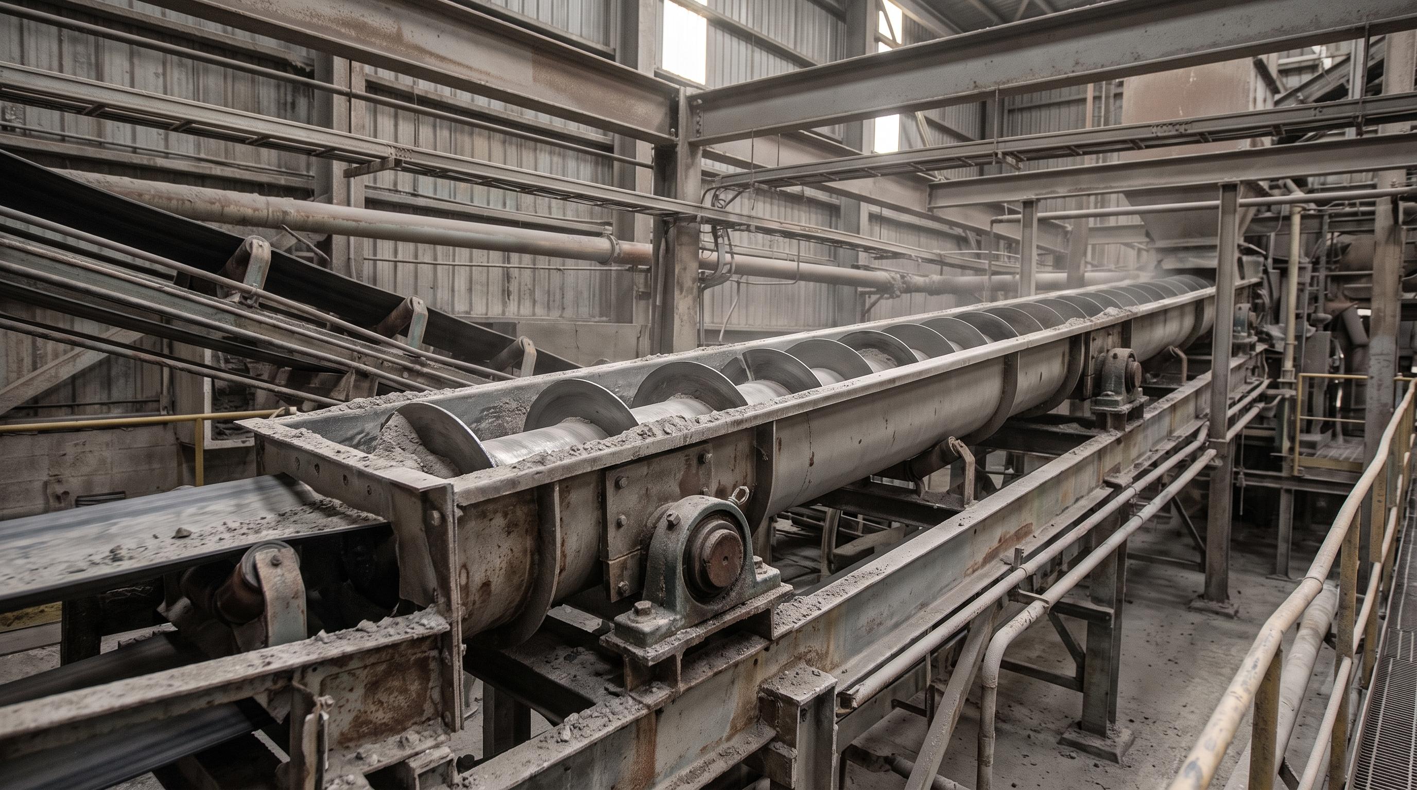
Good screw conveyor design starts with material behavior, then checks capacity, diameter, pitch, incline losses, drive power, and wear zones in sequence. Most plant failures come from sizing to catalog capacity, ignoring feed conditions, or underestimating wear and startup load. For cement, mining, and bulk handling plants, the best designs trade a little theoretical capacity for stable flow, lower maintenance, and longer service life.
Screw conveyors look simple, which is exactly why they are often under-engineered. Many plant teams treat them as standard utility equipment: choose a diameter, set a speed, and install a motor. That approach usually works only until the line sees wet ash, hot clinker dust, sticky fines, or inconsistent feed from an upstream hopper.
In practice, screw conveyor design is a balancing act between throughput, wear life, power draw, and flow stability. If the screw is too small, it chokes and overloads. If the speed is too high, it accelerates wear, aerates fine powder, and increases dust. If the pitch is wrong, the conveyor may roll material backward on an incline. If the shaft is too light, hanger spacing becomes a maintenance problem instead of a design feature.
Quick engineering rule: Do not ask only, “How many tonnes per hour do we need?” Ask, “What material are we moving, how does it behave, how far, at what incline, at what temperature, and how easy will this be to maintain after 18 months of plant service?”
What Is a Screw Conveyor and Where Does It Fit Best?
A screw conveyor uses a helical flight rotating inside a trough or tubular casing to push material forward. It is best suited for short to medium distances where enclosed transfer, controlled feed, and compact layout matter more than long-distance efficiency.
Screw conveyors are commonly chosen when the plant needs:
Enclosed conveying for dusty or fine materials
Short transfer distances between equipment
Controlled discharge into process equipment
Compact layout around tight plant spaces
Integrated metering with rotary valves, bins, or feeders
They are widely used in cement plants for fly ash, cement, and raw meal; in power plants for ash handling; in process industries for powders and pellets; and in wastewater or waste handling when shaftless designs are more suitable.
Where long horizontal distances dominate, a screw conveyor is often paired with a belt conveyor system instead of replacing it. The screw conveyor does the controlled, enclosed transfer. The belt conveyor handles long-distance movement more efficiently.
If you need a quick reference for sizing, layout reviews, or specification checks before release, a structured engineering summary helps align procurement and operations before the order is placed.
Types of Screw Conveyors
Horizontal Screw Conveyors
Horizontal screw conveyors are the most common design because they offer the highest conveying efficiency. Material settles naturally into the lower section of the trough, and the rotating flight advances it forward with relatively predictable loading.
Use horizontal designs when you need stable throughput with moderate power demand. They are common below silos, dust collectors, weigh hoppers, and transfer points. In cement and fly ash systems, horizontal units also help reduce fugitive material loss when compared with open transfer methods.
Inclined Screw Conveyors
Inclined screw conveyors are used when the layout needs elevation gain without switching to a bucket elevator or vertical lift system. The challenge is that capacity drops as incline increases because gravity works against the material column.
Incline | Typical Capacity vs Horizontal | Design Note |
|---|---|---|
10° | About 90% | Minor derating, standard pitch often works |
15° | About 70% | Check loading and drive torque carefully |
20° | About 50% | Short pitch often preferred |
25° | About 30% | Rollback becomes a major concern |
When the incline rises, power requirement goes up while usable capacity goes down. That is why steep inclined screw conveyors should never be sized from horizontal capacity charts alone. For a standards-based starting point on screw conveyor design and horsepower guidance, refer to CEMA technical resources before finalizing assumptions.
Vertical Screw Conveyors
Vertical screw conveyors are used for elevation in tight spaces, but they are much more application-sensitive. They perform best with free-flowing materials that can be lifted consistently inside a close-clearance casing. They are rarely the most forgiving choice.
Use vertical screws only after checking material flow behavior carefully. If the material is sticky, fibrous, or irregularly fed, a vertical screw becomes difficult to run reliably.
Shaftless Screw Conveyors
Shaftless screw conveyors remove the center shaft and are designed for sticky, stringy, or compressible materials that would wrap around a conventional shaft. They are common in sludge, screenings, fibrous waste, and some difficult process by-products.
They are not the default choice for every plant, but they are often the right one when buildup and wrapping would make a conventional screw unreliable.
How Screw Conveyor Capacity Is Calculated
Capacity is usually estimated from screw diameter, pitch, speed, and fill level. A widely used volumetric relationship is:
Q = (π/4) × D² × P × N × C × ψ × 60
Where:
Q = volumetric capacity in cubic meters per hour
D = screw diameter in meters
P = pitch in meters
N = rotational speed in RPM
C = geometry factor, commonly taken as 1.0 for standard assumptions
ψ = trough loading or fill factor
The important part is not memorizing the formula. It is choosing realistic loading values for the material. Free-flowing materials can tolerate higher loading than abrasive, sluggish, or degradable materials.
Typical loading guidance
15% fill: very abrasive, very hot, or degradation-sensitive materials
30% fill: many cement, ash, coal, and limestone duties
45% fill: freer-flowing, easier materials with lower wear risk
For example, a 300 mm screw running at 60 RPM with standard pitch and 30% loading gives a practical starting point for medium-duty powder handling. But that result still needs correction for incline, material friction, feed consistency, and operating margin.
How to Select the Right Screw Diameter
Screw diameter should be selected from required throughput, material bulk density, lump size, available speed range, and allowable wear rate. Bigger is not always better. Oversizing can reduce fill consistency and may create a bulky, slow-turning machine that still wears poorly if the inlet is wrong.
Screw Diameter | Typical Use | Typical Application Range |
|---|---|---|
150 mm | Low-capacity dosing | Small additives, laboratory or pilot duties |
200–250 mm | Light industrial transfer | Fine powders, feeder duties, ash or additives |
300–400 mm | Mainstream process transfer | Cement, fly ash, raw meal, moderate plant duties |
500–600 mm | Heavy bulk transfer | Coal, high-duty process handling, larger feed systems |
A good rule is to keep lump size well below the conveyor diameter. If large particles or compacted lumps are likely, diameter and pitch selection must leave enough room to avoid plugging.
How Drive Power Is Calculated
Drive power is driven by throughput, conveyor length, material density, and the effective resistance of the material inside the conveyor. A common practical form is:
P = (Q × L × W × Ff) / 367
Where:
P = power in kilowatts
Q = capacity in tonnes per hour
L = conveyor length in meters
W = bulk density in tonnes per cubic meter
Ff = material resistance factor
For inclined conveyors, add the lifting component as a separate power demand. Then add realistic allowance for bearing losses, startup conditions, and service factor.
Practical power selection approach
Calculate conveying power
Add incline or lift power if relevant
Add bearing and mechanical losses
Apply service factor for startup and upset conditions
Select the next standard motor size with operating margin
One of the most common design mistakes is selecting a motor from clean, steady-state math while ignoring sticky startup conditions. Plants do not start under textbook conditions. They start with real residue, inconsistent feed, and mechanical wear.
Screw Pitch, Flight Type, and Why They Matter
Standard Pitch
Standard pitch usually equals the screw diameter and works well for horizontal conveying of free-flowing materials. It offers good volumetric efficiency and is the most common general-purpose choice.
Short Pitch
Short pitch, often about two-thirds of standard pitch, improves control on inclines and helps reduce rollback. It is often selected for inclined screws, difficult materials, or where tighter material control matters more than pure volumetric efficiency.
Cut Flight
Cut flights include openings that help with mixing, agitation, or material release. They are useful when the conveyor must do more than simply push material forward.
Ribbon and Paddle Flights
Ribbon and paddle designs are selected when blending, stirring, or handling sticky material is more important than straight conveying efficiency. These are specialized choices and should be matched tightly to process need.
Design reminder: If the conveyor must handle incline, mixing, or sticky material, do not default to standard full-pitch flights. Flight style is often the difference between a conveyor that runs cleanly and one that becomes a permanent maintenance complaint.
Material Selection for Long Service Life
Material selection should follow the wear profile of the handled material, not just the initial equipment budget.
Component | Standard Duty | Abrasive Duty | Corrosive or Hygienic Duty |
|---|---|---|---|
Flights | Mild steel | Wear-resistant plate such as Hardox | SS 304 or SS 316 |
Trough | Mild steel | Wear liners or hard-facing zones | SS 304 or SS 316 |
Shaft or pipe | Standard carbon steel pipe | Heavier wall or solid shaft sections | Stainless construction as needed |
Hanger bearings | Bronze or ball bearing types | UHMWPE sleeves or sealed bearing solutions | Food-grade or corrosion-resistant materials |
For abrasive duties such as clinker, coal, or ash with hard fines, wear surfaces matter far more than they appear to on day one. The cheapest construction is often the most expensive once shutdowns, rebuilds, and lost production are considered. Where abrasion is severe, it also helps to review wear-resistant material guidance from manufacturers such as SSAB Hardox when comparing liner and flight options.
Selection Factors Engineers Should Review Before Finalizing a Design
Material behavior: free-flowing, cohesive, abrasive, hot, degradable, fibrous, or sticky
Bulk density: needed for mass-flow and power checks
Feed consistency: steady metered feed is very different from flood-fed loading
Incline angle: affects usable capacity and power
Required maintenance access: hanger inspection, cleanout, liner change, and coupling access
Dust control needs: especially in cement and fine powder applications
Integration with upstream and downstream equipment: hoppers, feeders, rotary airlock valves, transfer chutes, and belts
These are exactly the kinds of issues that tend to show up later as plant “operation problems” even though they were really design decisions from the start.
Common Screw Conveyor Design Mistakes
1. Using horizontal capacity assumptions on inclined conveyors
This is one of the most frequent errors. Incline reduces actual carrying efficiency quickly. If the conveyor angle rises, the calculation must be corrected.
2. Running too fast to recover capacity
Higher speed is an easy temptation. It can recover capacity on paper, but it often increases wear, dust, and material degradation in real service.
3. Ignoring inlet design
A screw conveyor is only as stable as its feed. Poor inlet design floods one section, causes uneven loading, and makes the drive look undersized even when the real issue is feed geometry.
4. Underestimating hanger bearing importance
Hanger bearings are not minor accessories. In long screws, they are one of the main reliability points. Poor spacing, weak sealing, or inaccessible maintenance points create avoidable failures.
5. Choosing materials for purchase price instead of duty
Mild steel flights in a highly abrasive application usually look economical only until the first rebuild cycle.
Operational Impact: What Good Design Improves
Design Area | If Done Poorly | If Done Well |
|---|---|---|
Diameter and speed | Choking, overload, fast wear | Stable flow and manageable wear |
Pitch and flight type | Rollback, poor control, plugging | Material matched to operating duty |
Material selection | Frequent rebuilds and downtime | Longer service life |
Inlet and discharge design | Flooding and erratic feed | Smoother process integration |
Maintenance access | Delayed inspections and breakdowns | Faster servicing and higher uptime |
Plants often focus on rated capacity, but the real value of good screw conveyor design is process stability. A conveyor that runs consistently with fewer interventions protects the rest of the line.
If your team is reviewing a new installation, frequent screw wear, startup overloads, or unstable ash, cement, or powder transfer, a design review usually saves more time and cost than repeated repair work.
Field Experience : At one cement plant handling fly ash from a hopper to a downstream dosing line, the original screw conveyor looked acceptable on paper but repeatedly tripped on startup. The issue was not just motor size. The unit had been sized close to peak demand, was flood-fed from above, and had insufficient allowance for compacted ash after short idle periods.
The fix involved three changes: reducing the effective startup burden with better feed control, revising the screw geometry for more stable loading, and increasing operating margin in the drive selection. After the changes, startup became repeatable, spillage around the transfer area dropped, and maintenance teams stopped treating the conveyor as a recurring nuisance.
Maintenance Priorities and Best Practices
Even a well-designed screw conveyor needs disciplined maintenance. The goal is to catch wear before it turns into secondary damage, while also keeping guarding and access practices aligned with OSHA conveyor safety requirements during inspection and service planning.
Inspect hanger bearings regularly: look for heat, noise, looseness, and contamination
Track flight wear: pay special attention near inlets, discharges, and high-impact zones
Check shaft alignment: misalignment increases bearing and coupling stress
Inspect trough wear: abrasive duties often wear the bottom first
Verify drive condition: couplings, gearbox mounts, and motor alignment affect long-term reliability
Control feed consistency: many “mechanical” problems begin as process feed problems
Plants that treat the screw conveyor as invisible until failure usually pay for it in emergency downtime.
How to Decide Between a Screw Conveyor and Other Conveying Methods
Choose a screw conveyor when you need enclosed transfer, controlled discharge, and compact routing over shorter distances. Choose a belt conveyor when distance and energy efficiency dominate. Choose other lift methods when vertical elevation is the main job and material behavior is difficult.
In many plants, the best answer is not one conveyor type instead of another. It is the right combination of equipment. For example, a screw conveyor may meter and enclose the discharge, while a belt system handles the longer run supported by properly selected idler standards and duty selection.
Final Takeaway
Screw conveyor design is not just about moving material from A to B. It is about matching conveyor geometry, speed, materials, and support details to how the bulk material actually behaves in your plant. When that match is correct, you get stable flow, manageable wear, lower downtime, and cleaner operation. When it is wrong, the conveyor becomes a source of plugging, overloads, dust, and repeated maintenance calls.
The most reliable designs start with the material, then check capacity, incline, power, shaft support, and wear zones in sequence. That is the practical route to a conveyor that works in plant conditions, not just in a catalog chart.
Frequently Asked Questions
The most important factor is material behavior. Capacity matters, but the design will fail if it ignores whether the material is abrasive, sticky, hot, fibrous, degradable, or prone to compacting.
Reduce wear by using realistic fill levels, controlling speed, choosing proper flight and trough materials, improving feed consistency, and inspecting hanger bearings and wear zones before damage spreads.
Capacity drops because gravity resists forward movement and promotes rollback. As the incline rises, the screw must do more lifting work, so usable carrying efficiency falls.
Use a shaftless screw conveyor for sticky, stringy, or compressible materials that would wrap around or build up on a conventional center shaft.
Sometimes for short enclosed transfers, yes. For long distances, a belt conveyor is usually more efficient. In many plants, the best solution is a combination of both.