
Slide Gate Valve for Bulk Material Handling: Types, Selection & Applications

Vijay Baid
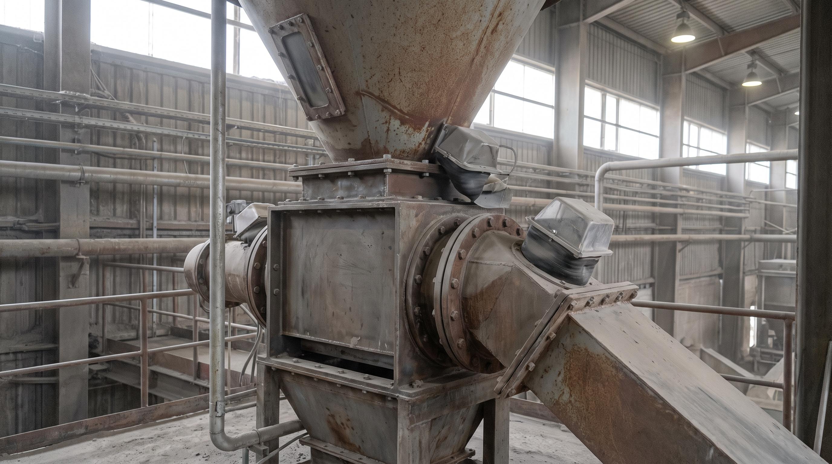
A slide gate valve controls or fully shuts off the flow of dry bulk material such as powders, granules, and pellets. To size it correctly, engineers need to match blade thickness to the material head load, choose seals that keep dust in, and select the right actuator. Manual drives suit low-cycle isolation. Pneumatic or electric drives suit faster or more controlled duty. A standard liquid knife gate usually fails quickly in dry bulk service because material packs into the seat, the blade binds, and the seals wear out fast.
In dry bulk solids handling, isolating a vessel or feeder is a basic requirement. This applies across mining, cement, plastics, food, and chemical plants. Slide gate valves are commonly installed under silos, hoppers, bin vents, bucket elevators, and screw feeders. In these positions, the valve acts as the main mechanical barrier in the line.
Unlike valves used for liquids, bulk material slide gates must move through a standing column of solids. Those solids may be fine powders, coarse minerals, or abrasive aggregates. The gate must open and close without jamming. It also has to keep dust from leaking into the plant.
When selected properly, a heavy-duty slide gate gives positive shut-off, protects downstream equipment during maintenance, and supports accurate batching. When selected poorly, problems start quickly. A low-cost liquid knife gate in a dry bulk line often leaks dust, traps material in the side guides, and causes the actuator to stall.
This comprehensive engineering guide breaks down valve mechanics, actuation styles, seal selections, actuation force calculations, and real-world failure prevention.
Working Principle: Linear Blade Displacement
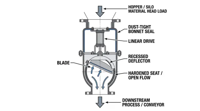
A bulk solids slide gate operates via linear mechanical displacement. A rigid metallic blade slides horizontally through a fully enclosed body frame to open or interrupt the vertical gravity flow path of bulk materials.
The Three Operational Regimes
Full Isolation (Maintenance Gate): Remains open 99% of the time during normal processing. It closes only to isolate a downstream rotary airlock or screw feeder during servicing.
On/Off Batching: Continuously cycles between fully open and fully closed to charge weigh hoppers or discharge batch mixers.
Flow Control (Metering): Utilizes variable positioning (e.g., electro-pneumatic positioners or multi-position air cylinders) to throttle material discharge rates.
Actuation Types & Comparison Matrix
Selecting the proper drive mechanism depends on cycle frequency, required closure speed, available plant utilities, and safety interlock protocols set by organizations such as OSHA (Occupational Safety and Health Administration).
Actuation Type | Best Used For | Operating Speed | Advantages | Limitations |
Manual Handwheel / Chainwheel | Maintenance isolation; infrequent cycling (< 1 time/day) | Slow (10-30 seconds) | Low capital cost; zero power consumption; failsafe mechanical hold. | Not suitable for automated processes; high operator effort under heavy head load. |
Pneumatic Cylinder | Automated batching; rapid cycling (> 50 cycles/day) | Fast (1-3 seconds) | Highly reliable; clean operating utility; rapid emergency fail-safe closure via air receivers. | Requires clean, dry, instrument-quality compressed air; prone to hard impact at end-of-stroke without cushions. |
Electric Motor Drive | Large apertures (> 600 mm); fine positioning control | Moderate (5-15 seconds) | Precise intermediate throttling control; high actuation force without pneumatic lines. | Higher initial capital cost; vulnerable to motor burn-out if blade jams on tramp metal. |
Hydraulic Cylinder | Heavy mining ores; extreme head-loads (> 3 bar) | Variable (2-8 seconds) | Extreme linear thrust capability; easily cuts through static head loads of dense material. | Risk of fluid leaks; requires dedicated hydraulic power unit (HPU) skid. |
Need assistance sizing a slide gate valve for an upcoming plant expansion? Download our comprehensive technical specification catalog or contact our engineering specialists for custom flange patterning and clearance analysis.
Mechanical Design Considerations & Sizing
To prevent mechanical failure, engineers must evaluate three primary design variables when specifying slide gates for bulk material lines:
1. Actuation Thrust Calculation (Fact)
The linear force required to move the slide gate blade through a standing column of material is a function of static head load pressure, material friction, and internal seal drag:
Fact = (Phead × Agate × μm) + (2 × Fseal) + Fmargin
Phead = Static bulk material head pressure (N/m²) = ρb × g × h
Agate = Cross-sectional area of the gate aperture (m²)
μm = Coefficient of friction between bulk material and blade surface (e.g., 0.35-0.55)
Fseal = Total mechanical compression friction from the internal packing glands (N)
Fmargin = Minimum safety factor allowance (1.5× to 2.0× calculated load)
2. Blade Deflection Limits
Under heavy material head-loads, thin blades flex downward. If deflection exceeds 1/500 of the span width, the blade will bind against the side seal guides, causing cylinder stalling and severe seal gouging.
Standard Duty: 304/316 Stainless Steel (6-9 mm thickness).
Heavy Duty / Mining: Hardox 400 or heat-treated carbon steel (12-25 mm thickness) with chamfered leading edges to shear through material pockets.
3. Dust Containment & Seal Material Selection
Fugitive dust emissions around the gate bonnet present environmental hazards and combustible dust explosion risks governed by NFPA 652.
UHMW-PE (Ultra-High Molecular Weight Polyethylene): Standard for non-abrasive powders up to 80°C; excellent low friction coefficient (μ ≈ 0.15).
Live-Loaded Braided PTFE / Graphite: Essential for elevated temperatures (150°C-250°C) or corrosive chemical environments.
Hardened Steel / Cast Iron Inverted V-Seats: Designed for highly abrasive clinker, fly ash, and minerals where soft elastomeric seals would erode in weeks.
Common Engineering Errors in Slide Gate Selection
Installing Liquid Knife Gates in Bulk Powder Applications: Liquid knife gates rely on a narrow metal-to-metal seat slot at the bottom of the body. Dry bulk powders fill this slot, compact into hard rock-like deposits, and prevent the blade from achieving full stroke closure.
Failing to Shield internal Bearings from Fines: Internal rollers supporting the blade must be sealed or placed outside the material flow stream. Fine dust invading unsealed rollers causes bearing seizure and blade jamming.
Ignoring Material Corrosion and Hygroscopic Clumping: Handling hygroscopic fertilizers or salt mixtures with plain carbon steel blades leads to rust scaling and material caking. Always specify 304 or 316 stainless steel blades with polished surfaces (Ra < 0.8 μm).
Undersizing Pneumatic Cylinders for Head-Load Startup: Sizing a cylinder based solely on empty-gate bench friction ignores the immense static friction when opening under a 10-meter silo head-load. Always apply a minimum 2.0× safety thrust multiplier.
Ready to optimize your material isolation systems? Contact our engineering technical team today to discuss your application parameters, request custom dimensional drawings, or receive an equipment quote.
Preventive Maintenance Checklist
To extend the operational lifespan of your slide gate valves and maintain dust-tight seals, follow this maintenance protocol:
Weekly: Inspect bonnet seal packing for visual dust puffing. Tighten gland adjustment bolts evenly if dust is observed.
Monthly: Drain pneumatic air filter-regulator-lubricator (FRL) bowls to ensure clean, moisture-free air reaches the actuation cylinder. Lubricate external drive screws or chain drives.
Quarterly: Check cylinder limit switches for tight position feedback alignment. Inspect blade leading edges through access ports for signs of severe erosion or deformation.
Annually: Measure internal UHMW-PE seal block thickness using feeler gauges. Replace packing seals if wear exceeds 2 mm.
System Integration Across Processing Equipment
Slide gate valves are critical isolation nodes across complex material handling networks. Ensuring seamless flange matching and flow capacities prevents process bottlenecks upstream and downstream.
Integrate your slide gate isolation units with downstream material handling equipment, such as heavy-duty Belt Conveyors, enclosed volumetric Screw Conveyors, material-metering Flow Control Gates, or process-routing Diverter Valves.
From the Field: A cement terminal had severe dust leakage from four 400 mm slide gates under limestone silos. The existing gates used felt packing seals. In this abrasive service, those seals wore out every two to three weeks. They also had no live loading, so seal pressure dropped as the blade cycled. That created a gap at the bonnet and allowed silo air pressure of 0.15 bar to blow dust into the plant. The gates were replaced with heavy-duty units using live-loaded UHMW-PE packing glands and hard-chrome plated 316 stainless steel blades. A deflector cone was also added above the blade opening to keep falling limestone away from the seal area. After the change, dust leakage stopped, seal life increased from about 3 weeks to more than 18 months, and maintenance labor fell by 82%.
Final Takeaway
Choosing the right slide gate valve is not just about picking a basic shut-off device. The valve must carry the material load above it, seal well enough to stop dust leakage, and move without jamming. That means engineers need to check head load, blade thickness, seal design, and actuator force before they decide. When those factors match the duty, the system runs safer, leaks less dust, needs less maintenance, and performs more reliably over time.
Frequently Asked Questions (FAQ)
A bulk solids slide gate is built to isolate or meter powders, granules, and other dry materials under head load, with sealing and blade support suited to dusty service. A standard knife gate valve is typically intended for liquid or slurry duty, so dry bulk material can pack into the seat area, increase friction, and cause rapid wear or failure.
Yes, but only when the valve is designed for metering duty and paired with the right actuator and controls. A gate built only for shut-off may wear quickly or deliver inconsistent discharge if it is used repeatedly in partially open positions.
Manual actuation suits isolation duties with very low cycling frequency, where simplicity matters more than speed. Pneumatic drives are the usual choice for fast automated batching, while electric drives fit larger openings and applications that need controlled intermediate positioning without plant air lines.
Dust leakage usually starts when bonnet packing wears down, compression on the seals is lost, or fine material enters areas it should not. Poor blade alignment, abrasive material, and pressure pulses from the silo or hopper can quickly enlarge small gaps and turn them into continuous leakage points.
In abrasive applications such as cement, clinker, and fly ash handling, inspect bonnet seals, blade edges, and guide areas weekly for wear, dust leakage, and buildup. A deeper mechanical inspection each quarter helps catch alignment issues, seal loss, and early blade damage before they cause jamming or unplanned shutdowns.